Elevated fixed-grate apparatus for use with multi-fuel furnaces

a multi-fuel furnace and fixed-grate technology, which is applied in the direction of lighting and heating apparatus, solid fuel combustion, combustion types, etc., can solve the problems of inability to purchase small wood products manufacturing operations, the style of combustion device is typically extremely expensive, and the fuel supply arrangement is contrastically complicated. , to achieve the effect of avoiding rapid wear and constant maintenan

Active Publication Date: 2015-04-07
PLAYER TYLER MARSHALL
View PDF25 Cites 2 Cited by
  • Summary
  • Abstract
  • Description
  • Claims
  • Application Information

AI Technical Summary

Benefits of technology

[0010]It is an object of the present invention to obviate or mitigate at least one disadvantage of previous combustion devices. The present invention provides the benefit of proper de-ashing online while distributing the underfire air radially around the pile. The elevated design of the bricks allows the air to be evenly distributed throughout the fuel pile and further allows the isolation of overfire and underfire air. Segregating overfire and underfire air in an evenly distributed manner allows the burner to combust a wide range of fuel moisture contents without modifying the mechanical components of the burner. Using bricks eliminates the problems created by using metal based grates in the floor of the furnace, thus avoiding rapid wear and constant maintenance during the burn of low moisture content fuel.
[0011]In general, the present invention includes a round vertical combustion chamber. The chamber is composed of several isolated sections that are fed through an air header and controlled through damper actuators. The grate bricks are arranged in a radial fashion and elevated to allow smooth airflow throughout the pile. This also allows proper three-stage combustion of the wood fuel whereby drying, gasifying, and heat release all occur in an appropriate fashion across the grate area. Thus, this grate area is specifically designed for a wide range of moisture in the fuel supplied. The inventive configuration of elevated bricks is arranged in a radial pattern so as to solve the problems of both isolating underfire / overfire air and of automatic de-ashing. The elevated configuration allows maximization of the air flow through the grate area without compromising the high heat capability of refractory. This allows the inventive device to burn low moisture fuel without damaging the grate. Moreover, the present invention as claimed provides an invention that materially enhances the quality of the environment by materially contributing to the more efficient utilization and conservation of energy resources by using, with high efficiency, wood waste from the wood manufacturing industry.

Problems solved by technology

The online de-ashing avoids problems associated with a fixed floor furnace, but creates a furnace that cannot burn excessive amounts of dry fuel without the need of wetting the fuel or something similar that drastically complicates the fuel supply arrangement to these combustion devices.
In addition, this style of combustion device is typically extremely expensive due to the metal bars in the floor.
This is impractical for small wood products manufacturing operations to purchase.
While many such solutions exist to the combustion of wood and waste, problems are common to most every configuration of walking grates, fixed floor grates, and fixed floor bins.
For example, walking grates do not allow the burning of fuel below 40% moisture content without damaging the metal grates.
As well, fixed floor grates often plug and are hard to clean and properly gasify the products of combustion without a mechanically large furnace area.
Still further, fixed floor bins are nearly impossible to effectively de-ash while online and prove very difficult to keep air infiltration down.

Method used


Image

  • Elevated fixed-grate apparatus for use with multi-fuel furnaces
  • Elevated fixed-grate apparatus for use with multi-fuel furnaces
  • Elevated fixed-grate apparatus for use with multi-fuel furnaces

Examples


Embodiment Construction

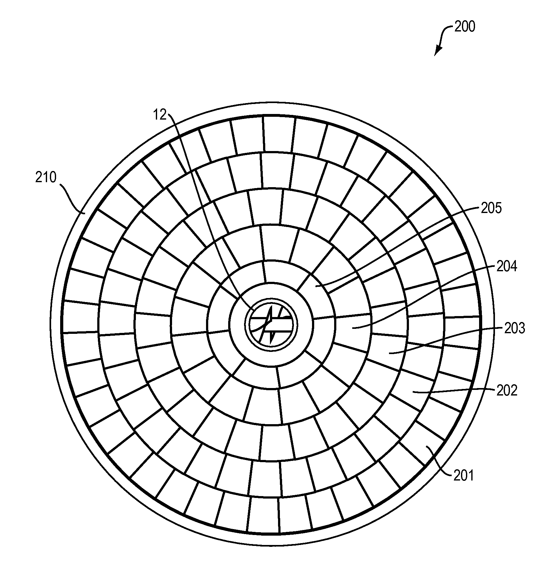
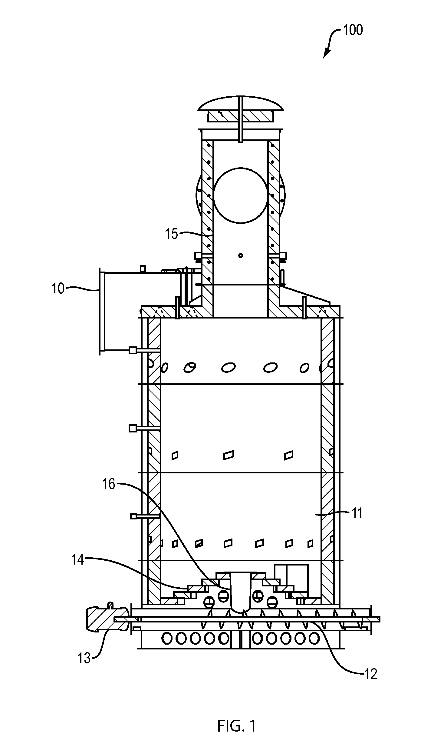
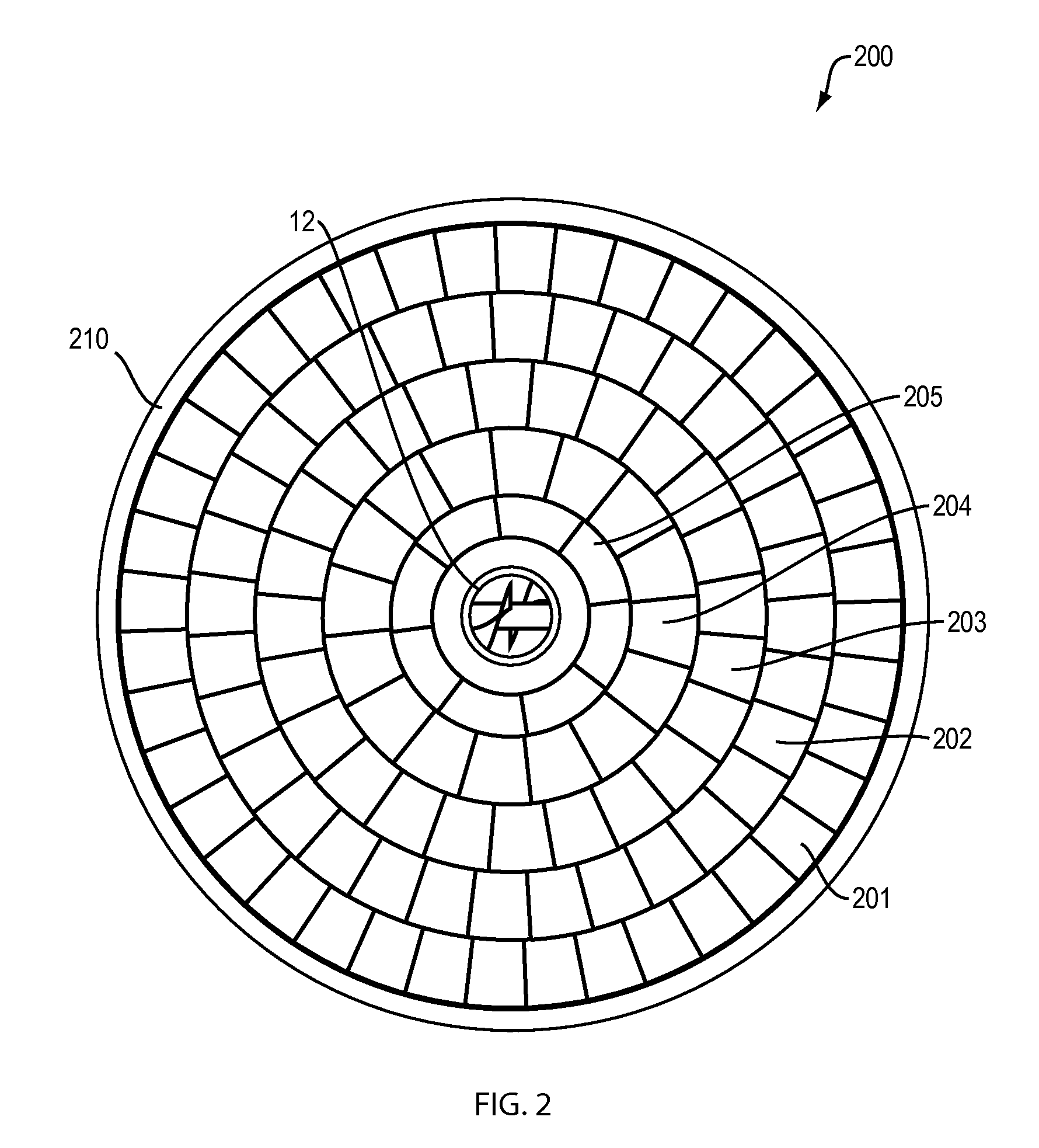
[0025]Generally, the present invention provides a combustion apparatus in the form of a multi-fuel furnace with an inventive fixed-grate that is elevated and center-fed with wood fuel. With specific reference to FIG. 1, there is shown a generalized schematic of a multi-fuel furnace 100 with an elevated fixed-grate 14 in accordance with the present invention. It should be understood that a variety of furnace configurations may be possible without straying from the intended scope of the present invention and that the configuration shown in FIG. 1 is only one possible configuration. Here, basic furnace elements are illustrated including an auger mechanism 12 powered by motor 13 for providing a center-fed input of combustible fuel such as, but not limited to, waste wood, sawdust, wood chips, bark, or any residual waste product from wood manufacturing. The inventive fixed-grate provides enhancements a multi-fuel furnace which helps to improve the overall quality of the environment. This ...


PUM


Abstract

A combustion device in the form of an elevated fixed-grate that includes arcuately shaped solid refractory brick with ribs placed thereunder so as to allow horizontal air flow for fuel combustion. The brick are arranged atop one another in a stacked concentric configuration that forms a central fuel passageway and allows cascading of a fuel pile throughout the combustion stages. The device provides the benefit of proper de-ashing online while distributing the underfire air radially around the fuel pile. The elevated design of the bricks allows the air to be evenly distributed throughout the fuel pile and further allows the isolation of overfire and underfire air. Segregating overfire and underfire air in an evenly distributed manner allows the burner to combust a wide range of fuel moisture contents without modifying the mechanical components of the burner.

Description

FIELD OF THE INVENTION[0001]The present invention relates generally to carbon-based fuel furnaces. More particularly, the present invention relates to an improved grate configuration to enhance combustion of fuel of varying quality.BACKGROUND OF THE INVENTION[0002]In the art of wood and waste combustion systems, a variety of well known techniques and devices are available for heat generation of various kinds. In particular, the wood products manufacturing industry includes combustion techniques and devices which include heat sources for drying equipment. Oftentimes, such combustion techniques and devices are intended to burn all kinds of wood and potentially other solid-carbon-based fuel sources. Such varying fuel sources include waste that is sourced from wood products manufacturing. Not only do the fuel sources vary in composition and physical form, but such fuel sources also vary considerably in terms of moisture content. Accordingly, within this field, there have been many devic...

Claims


Application Information

Patent Timeline
Patent Type & Authority Patents(United States)
IPC IPC(8): F23B60/00F23B40/04F23L9/06F23J1/00
CPCF23B60/00F23B40/04F23L9/06F23J1/00
Inventor PLAYER, TYLER MARSHALL
Owner PLAYER TYLER MARSHALL
Why Eureka
Try Eureka