Two-piece ball bat with rigid connection

a two-piece ball bat and rigid connection technology, applied in the field of ball bats, can solve the problems of poor material for the player's hands to hold and grip, difficulty in manufacturing mechanical joints, and common problems in the barrel region to achieve the effect of providing durability and strength

Inactive Publication Date: 2008-03-13
NIKE INC
View PDF15 Cites 24 Cited by
  • Summary
  • Abstract
  • Description
  • Claims
  • Application Information

AI Technical Summary

Benefits of technology

[0011]The rigid connection between the barrel and handle of the present invention maximizes the conservation of collision energy upon impact with the ball to enable better performance. The combination of the interference fit and the rigid adhesive ensures that less of the collision energy is lost to damping as is the case with elastomeric joints.
[0013]In one aspect of the invention, the barrel is made of a metal to provide the durability and strength necessary for the ball impact area, while the handle is made of a composite to provide opportunities to tune the performance of the bat depending on player's skill level and strength.

Problems solved by technology

A single material may present advantages for hitting, for example, but be a poor material for the player's hands to hold and grip, especially upon impact.
For example, there have been prior art ball bats made entirely of a single composite material, but durability in the barrel region has been a common problem.
Mechanical joints complicate manufacture as they require more manufacturing steps; introduce more quality control factors for fit and finish; increase the chances of mis-assembly; potentially increase tolerance build-up; and may require more assembly steps to complete a ball bat.
Higher complexity translates to higher cost with respect to tooling, efficiency and labor.

Method used


Image

  • Two-piece ball bat with rigid connection
  • Two-piece ball bat with rigid connection
  • Two-piece ball bat with rigid connection

Examples


Embodiment Construction

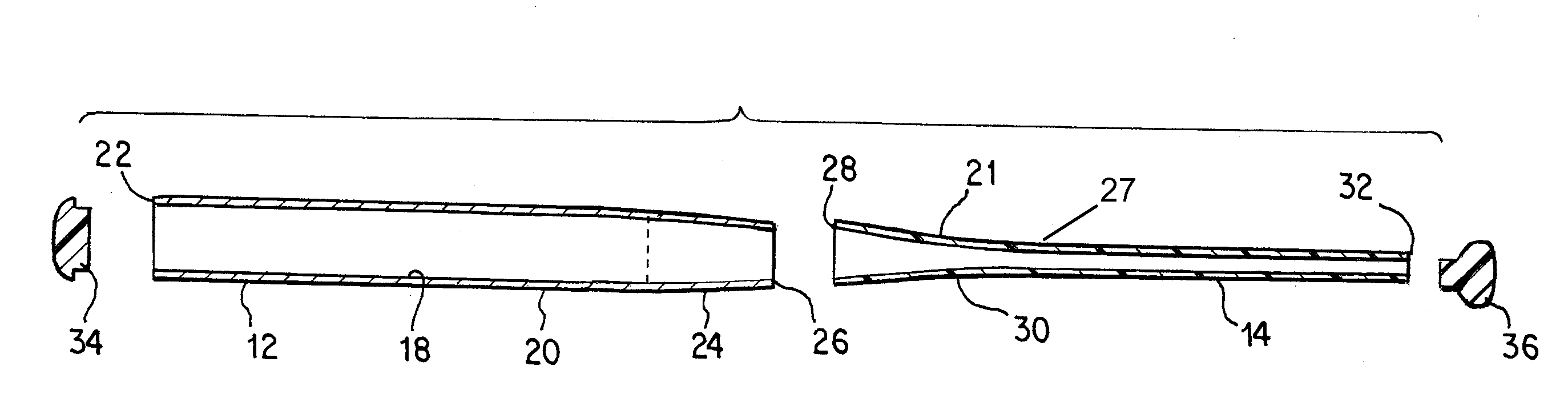
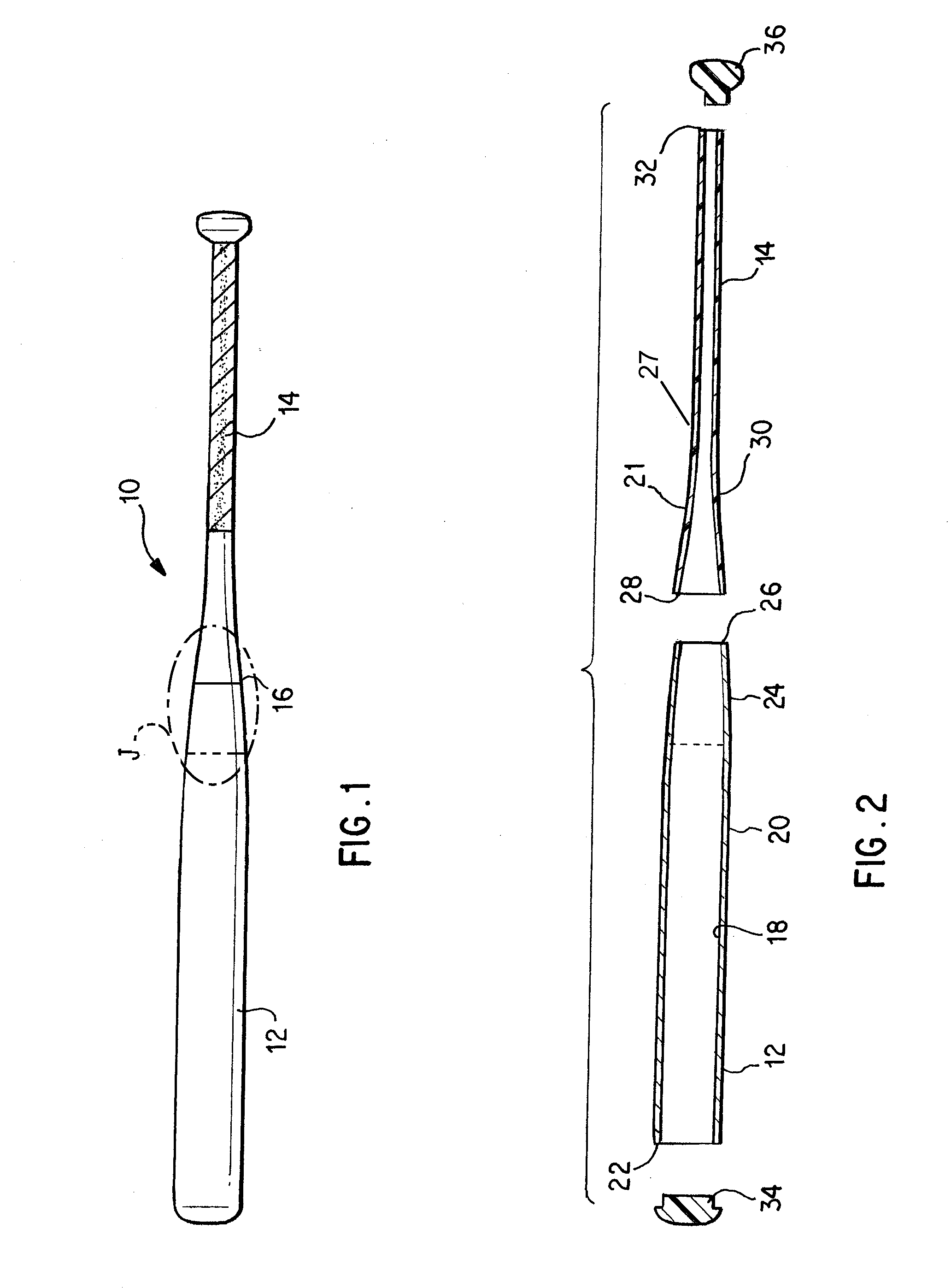
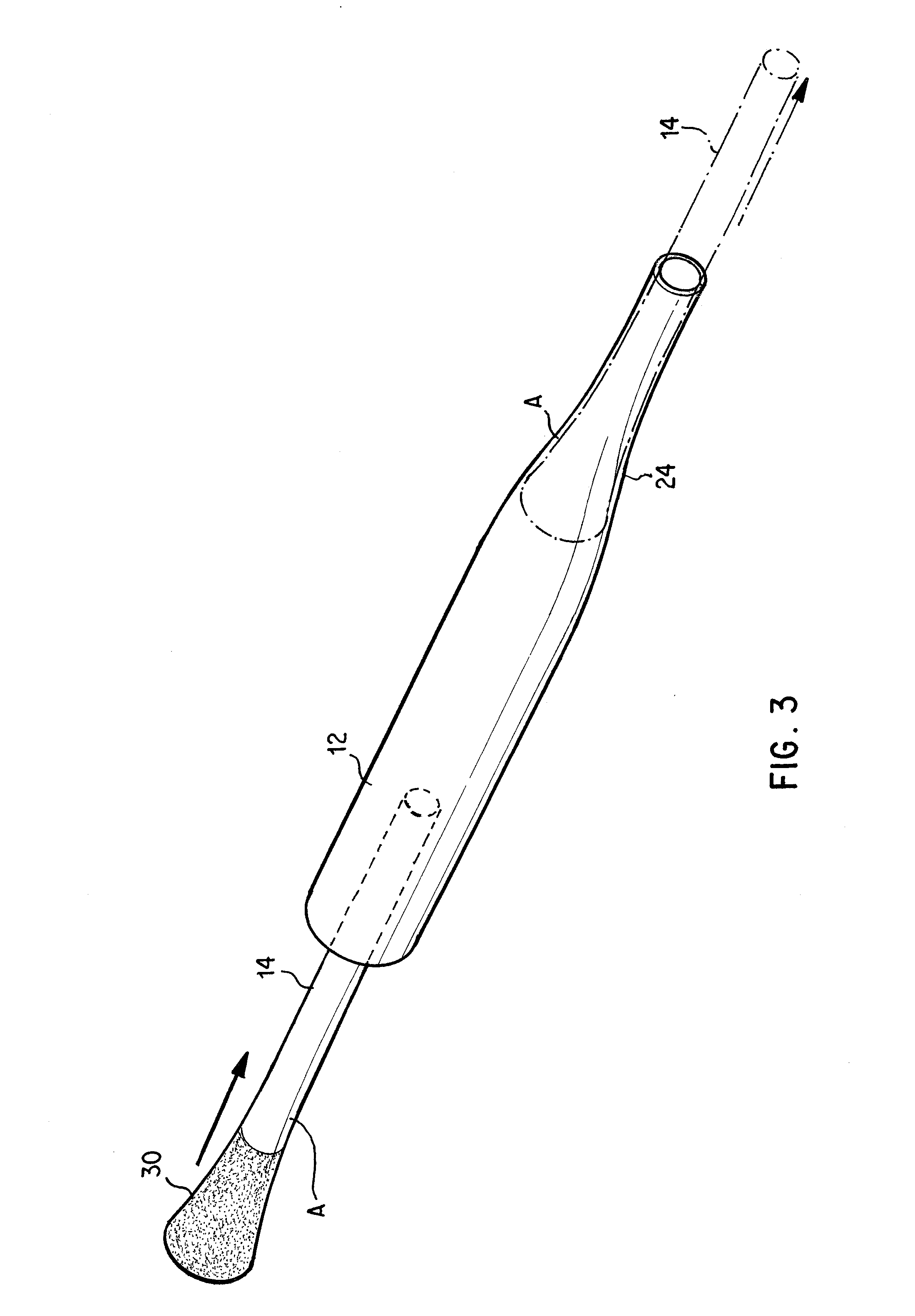
[0024]FIG. 1 shows assembled ball bat 10 comprising a barrel 12 and a handle 14 attached to one another at a taper junction 16. Taper junction 16 is the transition between the larger circumference barrel and smaller circumference handle. FIG. 2 shows in exploded cross-section the components of the ball bat. Specifically that barrel 12 is a hollow body with an interior surface 18 and an exterior surface 20. Along its length barrel 12 has a distal free end 22, a taper section 24, and a proximal joint end 26. Barrel 12 has a larger diameter at its distal free end 22 and a smaller diameter at its proximal joint end 26. Taper section 24 provides a smooth transition between these two circumferences. Exterior surface 20 of the barrel is the ball contact surface. Handle 14 is shown in FIG. 2 to be a hollow body, but could be solid. Handle 14 has an exterior surface 27 and includes along its length, proximal joint end 28, a taper section 30 and a distal free end 32. Joint end 28 of handle 14...


PUM


Abstract

A two-piece ball bat comprising a hollow barrel attached to a handle by a combination of mechanical interference and a layer of rigid adhesive interposed between the interior surface of the barrel and the exterior surface of the handle at a tapered junction. The rigid adhesive layer prevents any direct contact between the barrel and handle thereby eliminating the need to provide any mating features thereon and reducing complexity and cost of manufacture. In an alternative embodiment, glass shafting beads are added to the rigid adhesive compound to ensure even distribution of the adhesive compound, align the barrel and handle and ensure separation prior to curing.

Description

BACKGROUND OF THE INVENTION[0001]1. Field of the Invention.[0002]This invention relates to a ball bat having a ball bat barrel connected to a bat handle by a combination of mechanical interference and rigid adhesive without the barrel and handle being in direct contact, and a method for making same.[0003]2. Background of the Invention.[0004]Ball bats for baseball and softball generally have a similar shape and comprise a handle, a barrel and a taper that smoothly transitions between the larger circumference barrel and the smaller circumference handle. The handle is sized for a player to easily and securely grip the bat, and usually includes a tape or wrapping to enhance the grip of a player's hands. The barrel is the ball contact portion. The holding and gripping of the bat is a much different purpose than hitting a ball, but many baseball and softball bats are made of a single material, typically aluminum or wood. A single material may present advantages for hitting, for example, b...

Claims


Application Information

Patent Timeline
Patent Type & Authority Applications(United States)
IPC IPC(8): A63B59/00
CPCA63B59/06A63B2102/18A63B59/50A63B2102/182A63B59/51A63B60/08A63B60/16
Inventor MCNAMEE, MARKPAGE, CHRISTOPHER
Owner NIKE INC
Why Eureka
Try Eureka