Plungers Helper

Inactive Publication Date: 2008-03-20
MOONEY ROBERT BLU
View PDF3 Cites 3 Cited by
  • Summary
  • Abstract
  • Description
  • Claims
  • Application Information

AI Technical Summary

Benefits of technology

[0011] In accordance with its design, the Plungers Helper is a hard type shell cup like apparatus. It has sealing means on the leading circular lips edge. On the opposing side is a handle that is attached to the cup by a securing means also may be used without a

Problems solved by technology

There is no existing product that would be used for

Method used


Image

  • Plungers Helper
  • Plungers Helper
  • Plungers Helper

Examples


Example

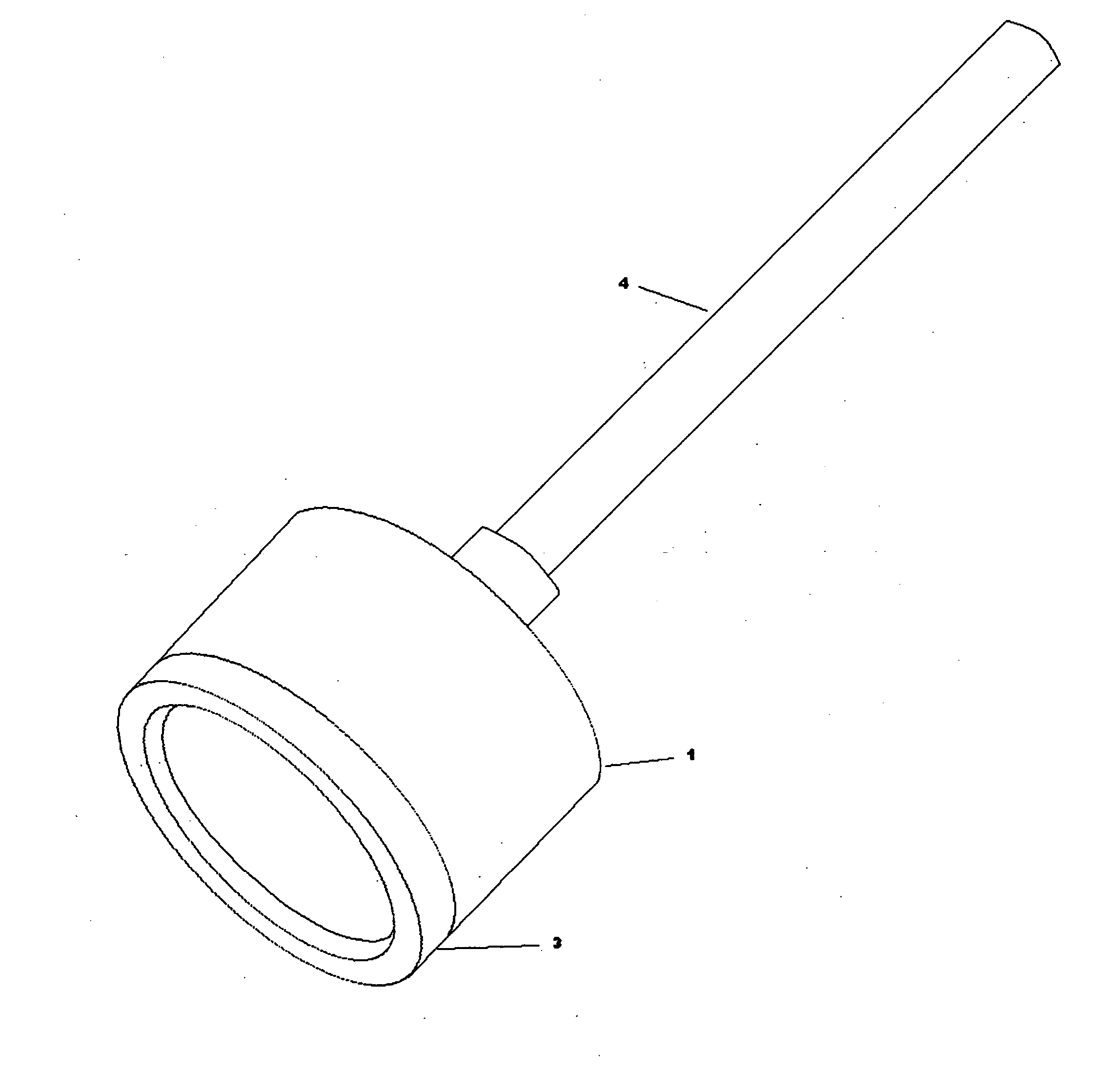
[0016] 5a. Diagram Page 1, FIG. C-1 Side View, Shows plain handle for cup body, compression cup can be used with no handle.

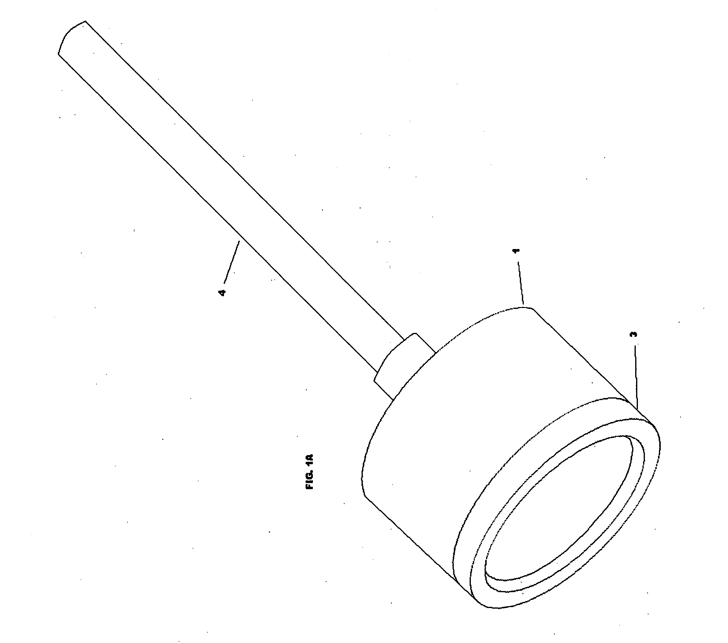
[0017] 6a. Diagram Page 1-A Shows 3 dimensional of diagram page 1

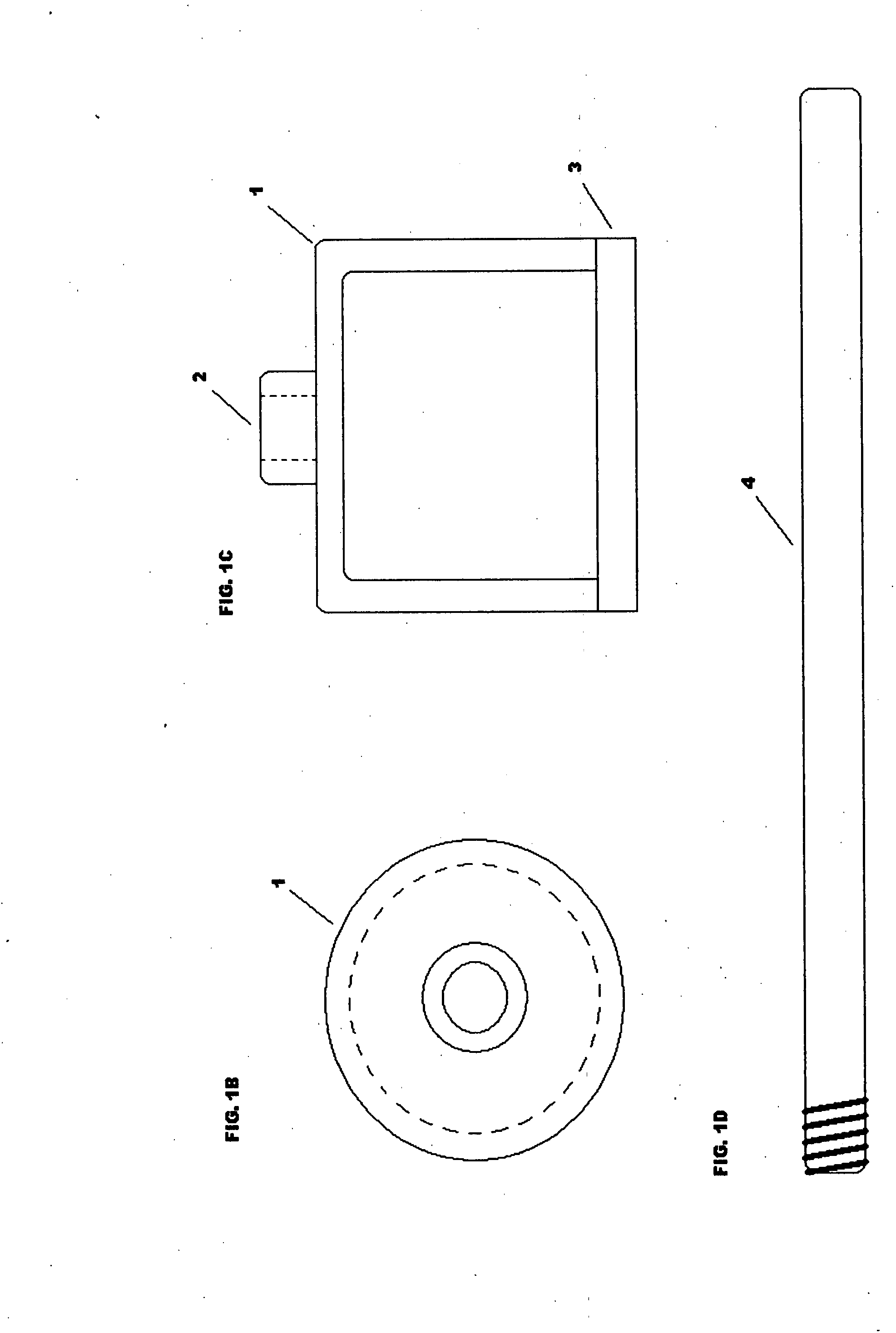
[0018] 1b. Diagram Page 2, FIG. A-1 Top view, Compression cup body.

[0019] 2b. Diagram Page 2, FIG. B-1 Side View, Compression cup body with alternative reinforced embodiment.

[0020] 3b. Diagram Page 2, FIG. B-2 Side View, Placement hole for handle centered in reinforced compression cup body.

[0021] 4b. Diagram Page 2, FIG. B-3 Side View, Compression cup body rim seal with sealing means.

[0022] 5b. Diagram Page 2, FIG. C-1 Side View, Shows handle for cup body with alternative handle grip with attaching means or compression cup may be used with no handle.

[0023] 6b. Diagram Page 2-A Shows 3 dimensional of diagram page 2

[0024] 1c. Diagram Page 3, FIG. A-1 Top View, Compression cup body shows alternative embodiment location for attaching handle.

[0025] 2c. Diagram Page 3, FIG. B-1 Side View, Compress...


PUM


Abstract

In accordance with its design the Plungers Helper is a hard type shell cup like apparatus. It has sealing means on the leading circular lips edge. On the opposing side is a handle that is attached to the cup by a securing means also may be used without a handle. This is then used to cover the orifice or overflow vent and is designed to achieve an air tight seal over the orifice or overflow vent. Then a plunger or alternative propelling devise is then used on the drain orifice to evacuate a clog or blockage of material substances.

Description

CROSS-REFERENCE TO RELATED APPLICATION [0001] This application claims the benefit of provisional patent application Ser. No. 60 / 836,237 filed 2006 Aug. 9 by the present inventor.FEDERALLY SPONSORED RESEARCH [0002] Not Applicable SEQUENCE LISTING OR PROGRAM [0003] Not Applicable BACKGROUND [0004] 1. Field of Invention [0005] This invention relates to plunging of plumbing drain related fixtures, to assist in the unclogging of drains. BACKGROUND [0006] 2. Prior Art [0007] There is no prior art, I have searched all the home improvement stores and Hardware stores. There is no existing product that would be used for what my “Plungers Helper” would do for the consumer. I have searched the USPTO extensively and have not seen a product that is like or made for what my product does. Therefore I have made this statement of no prior art. Produce Description and Usage [0008] The Plungers Helper is a tool for use in conjunction with a plunger or a related tool that is used in place of a plunger. ...

Claims


Application Information

Patent Timeline
IPC IPC(8): A47K1/14
CPCE03C1/24
Inventor MOONEY, ROBERT BLU
Owner MOONEY ROBERT BLU
Why Eureka
Try Eureka