Mass flow meter with solder/braze-flow secured spacer

Inactive Publication Date: 2009-10-22
SIERRA INSTR
View PDF5 Cites 43 Cited by
  • Summary
  • Abstract
  • Description
  • Claims
  • Application Information

AI Technical Summary

Benefits of technology

[0017]The present invention offers a mode of device construction in connection with thin-film RTD sensors that is able to leverage the cost advantage offered by such products, but still attain the measurement quality required of scientific and industrial applications. Namely, systems according to the present invention offer performance with as low as about 1% to about 2% of reading error in accuracy over a mass flow rate range of about 10% to about 100% of full scale (or lar

Problems solved by technology

Because the parts of the heated sensor of known thermal anemometers are not sufficiently reproducible dimensionally or electrically, known thermal anemometers require multi-point flow calibration of electrical output versus mass flow rate, usually in the actual fluid and with the actual ranges of fluid temperature and pressure of the application.
In such a system, “skin resistance” and stem conduction are two major contributors to non-ideal behavior and measurement errors in thermal anemometers constructed in this manner.
Skin resistance (in units of degrees Kelvin per watt) results in a temperature drop between the encased heated sensor and the external surface of the housing which increases as the electrical power supplied to the heated sensor increases.
Skin resistance creates a “droop” and decreased sensitivity in the power versus fluid mass flow rate calibration curve, especially at higher mass flow rates.
The droop is difficult to quantify and usually varies from meter to meter because of variations both in the parts of construction and in installation.
The ultimate result of these skin-resistance problems is reduced accuracy.
Furthermore, the use of a surrounding potting compound can create long-term measurement errors caused by aging and by cracking due to differential thermal expansion between the parts of the h

Method used


Image

  • Mass flow meter with solder/braze-flow secured spacer
  • Mass flow meter with solder/braze-flow secured spacer
  • Mass flow meter with solder/braze-flow secured spacer

Examples


Embodiment Construction

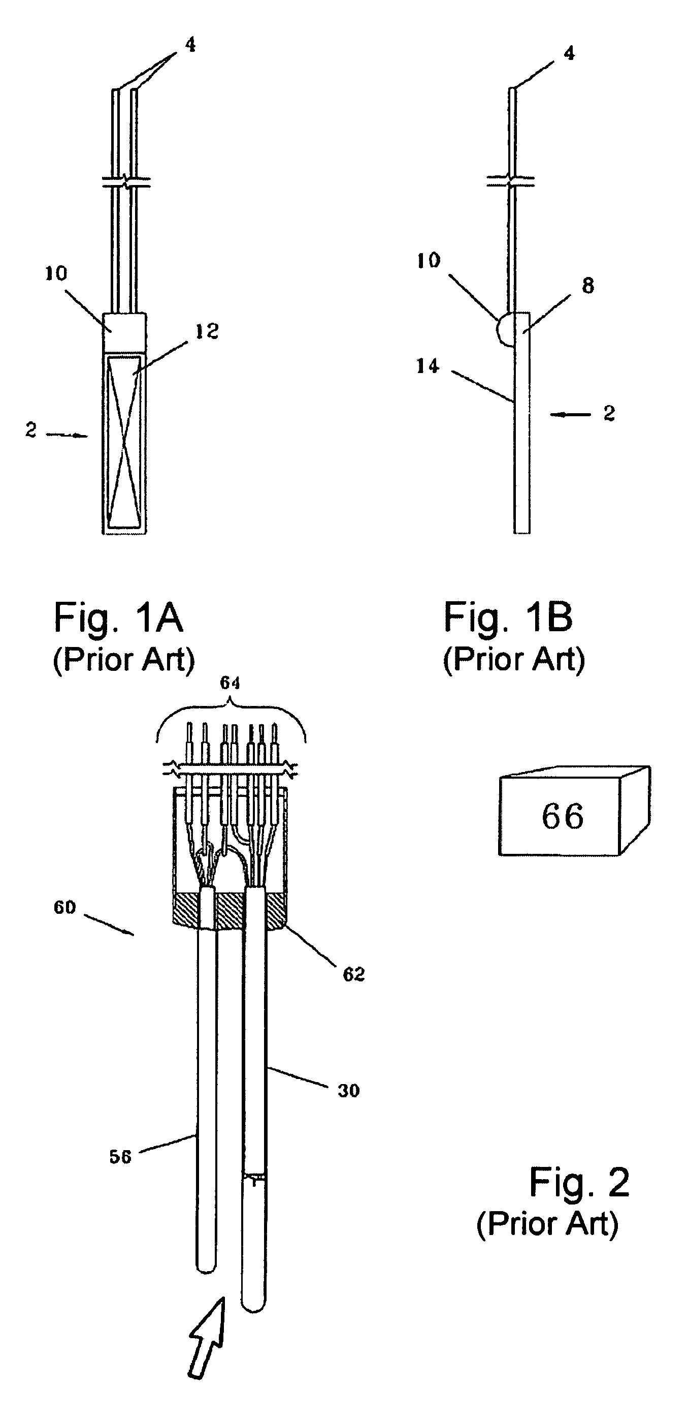
[0039]Turning now to FIGS. 1A and 1B, these show a view of the type of temperature sensor 2 employed in the present invention. The sensor shown is a “thin film” type sensor as described above. The particular sensor shown is a Thin-Film Platinum Resistance Temperature Detector (TFPRTD) as commonly available. An active area 12 of the device is provided, over which area the TFPRTD is self-heated by current during use. Sensor 2 includes lead wires 4 connected to weld pads leading to active region 12 and covered by a glass strain relief 10. The body 8 of the sensor is made of high-purity alumina, preferably held to a thickness tolerance within about ±0.002 to 0.001 inches as commonly available. A thin layer of glass electrical insulation 14 is provided over the TFPRTD active area. Of course, the PRTD is only exemplary as other TFRTDs may be employed in the invention. For example, other thin-film RTDs optionally employed in the invention may utilize nickel or other metals for the devices'...


PUM

PropertyMeasurementUnit
Lengthaaaaaaaaaa
Diameteraaaaaaaaaa
Temperatureaaaaaaaaaa

Abstract

A thermal anemometer or mass flow meter typically having temperature and flow velocity sensor elements is provided in which a thin film temperature sensor is used in the heated sensor of the fluid velocity sensor element of the system. At least one thin-film RTD sensor is held within a spacer or interface member and the spacer, optionally, received within a housing. The thermal anemometer is preferably constructed to offer sufficient precision and accuracy in its design to be suitable for sensitive scientific and industrial applications. This goal is achieved while using cost effective parts by employing a construction approach in which the spacer and RTD sensor(s) is secured in place by solder, braze or another compound flowed into place while inserting the spacer and/or sensor(s).

Description

FIELD OF THE INVENTION[0001]This invention relates to mass flow meters, particularly regarding their manufacture at decreased cost, yet of such quality for critical applications.BACKGROUND OF THE INVENTION[0002]The mass flow rate of a fluid (defined by its average velocity multiplied by its mass density multiplied by the cross-sectional area of the channel through which the flow travels) is a measured quantity of interest in the control or monitoring of most practical and industrial applications, such as any chemical reaction, combustion, heating, cooling, drying, mixing, fluid power, etc. Generally speaking, a thermal anemometer is used to measure the mass velocity at a point or small area in a flowing fluid—be it liquid or gas. The mass velocity of a flowing fluid is its velocity referenced to standard or normal temperature and pressure. The mass velocity averaged over the flow channel's cross-sectional area multiplied by the cross-sectional area is the standard or normal volumetr...

Claims


Application Information

Patent Timeline
IPC IPC(8): G01F1/68B23K31/02
CPCG01F1/684G01P5/12G01P1/026G01F1/692
Inventor OLIN, JOHN G.SMITHERMAN, JOHN P.
Owner SIERRA INSTR
Why Eureka
Try Eureka