Device and method for calibrating a pipette or a dispensing system

a technology for pipette or dispensing system, applied in the direction of volume measurement apparatus/methods, capacity measurement calibration, liquid/fluent solid measurement, etc., can solve the problems of high cost, rather expensive, and inability to meet the requirements of standard laboratory balance, etc., and achieve the effect of relatively economic manufactur

Active Publication Date: 2008-03-20
CSEM CENT SUISSE DELECTRONIQUE & DE MICROTECHNIQUE SA RECH & DEV
View PDF22 Cites 12 Cited by
  • Summary
  • Abstract
  • Description
  • Claims
  • Application Information

AI Technical Summary

Benefits of technology

[0005] It is an object of the invention to provide a device for calibrating a pipette or dispensing system that can be manufactured relatively economically. It is a further object of the invention to provide a device for calibrating a pipette or a dispensing system and a corresponding method for calibrating a pipette or a dispensing system that can be employed without the density of the fluid to be measured to be known in advance.

Problems solved by technology

The inherent uncertainties of the gravimetric method, at least when performed with standard laboratory balances, can become quite excessive.
In such cases properly calibrated so-called micro-balances can be used which, however, are rather expensive.
Colorimetric and gravimetric devices for pipette calibration are usually relatively expensive, and the usage for small volume calibration can be rather limited because of evaporation issues.

Method used


Image

  • Device and method for calibrating a pipette or a dispensing system
  • Device and method for calibrating a pipette or a dispensing system

Examples


Embodiment Construction

)

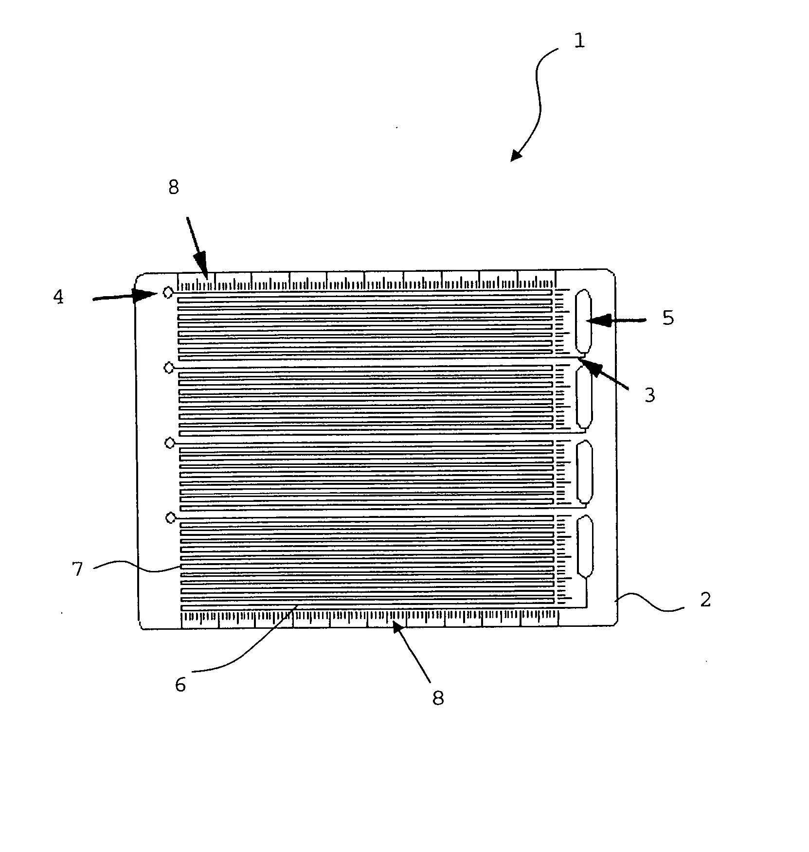
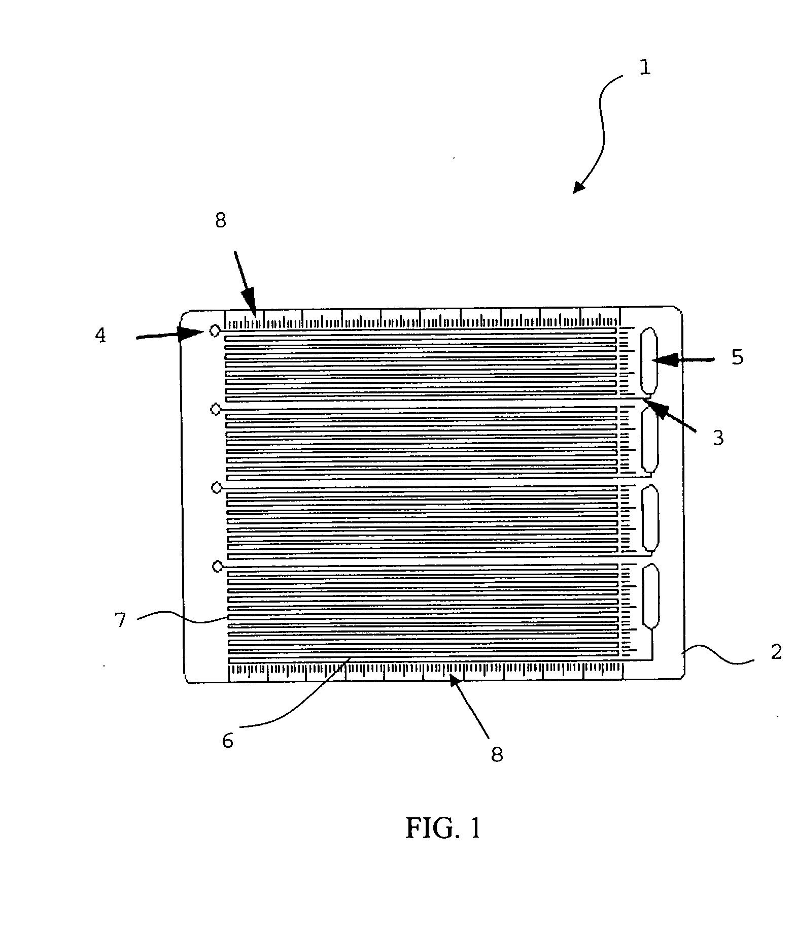
[0020] Device 1 for calibrating a pipette or a dispensing system comprises a plate 2 with four channels 3 within the shown surface of plate 2. Each channel 3 is assigned a loading port 4 and an excess fluid reservoir 5. By providing several channels 3 with corresponding loading ports 4 and excess fluid reservoirs 5 several pipettes or dispensing systems can be calibrated simultaneously. Loading ports 4 may for example have an inner diameter of 1 millimetre. They can be enlarged, preferably on one side, with a cone-shaped opening.

[0021] Channels 3 preferably take the course of a meander, the meander having longitudinal parts 6 and transverse parts 7 with transverse parts 7 preferentially being shorter than longitudinal parts 6. Of course, a channel 3 can also be constructed as one single line i.e. a single longitudinal part 6. Channels 3 preferably have no sharp edges. Possible bends of channels 3 are smooth or continuous, respectively. Longitudinal part 6 (including the transition...


PUM


Abstract

The present invention relates to a device (1) for calibrating a pipette or a dispensing system comprising a plate (2), said plate (2) comprising at least one channel (3) with a loading port (4) for receiving a test volume of a fluid at one end of the at least one channel and an opening (5) at the other end of the at least one channel, wherein the at least one channel (3) is constructed as a capillary. Furthermore, the invention relates to a method for calibrating a pipette or a dispensing system, comprising the steps of introducing a first volume of a fluid into a loading port (4) of a device (1), recording a first length of the fluid column in a channel (3) of the device (1), introducing a second volume of a fluid from the pipette or the dispensing system to be calibrated to the same loading port (4), recording a second length of the fluid column in the channel (3), and computing the volume dispensed by the pipette or the dispensing system by calculating the distance between the second length and the first length and multiplying said distance with the cross-section of the channel (3).

Description

FIELD OF THE INVENTION [0001] The present invention relates to a device for calibrating a pipette or a dispensing system and to a method for calibrating a pipette or a dispensing system. DESCRIPTION OF THE PRIOR ART [0002] Existing techniques for calibrating pipettes are generally based on the so-called gravimetric analysis. Samples of distilled water are dispensed into a receiving vessel that is perched atop a precision analytical balance. The density of water constitutes a well known constant and the weight of the dispensed sample provides an accurate indication of the volume dispensed. A condition for applying the gravimetric method is that the density of the fluid to be measured is known in advance. The gravimetric method is especially suited for calibrating low-volume pipettes in the region of less than two microlitres. The inherent uncertainties of the gravimetric method, at least when performed with standard laboratory balances, can become quite excessive. In such cases prope...

Claims


Application Information

Patent Timeline
Patent Type & Authority Applications(United States)
IPC IPC(8): G01F25/00
CPCB01L3/021B01L3/5027G01F25/0092B01L2200/148B01L2300/028B01L99/00
Inventor SCHMID, NOAAUERSWALD, JANKOSTOCKLI, THOMASKNAPP, HELMUT
Owner CSEM CENT SUISSE DELECTRONIQUE & DE MICROTECHNIQUE SA RECH & DEV
Why Eureka
Try Eureka