
Combination animal grooming and de-shedding tool

a technology of combination tools and tools, applied in the field of combination tools, can solve the problems of carpel tunnel syndrome, two separate tools can become difficult, and the skin is abrasive,

Inactive Publication Date: 2008-03-20
ROSEN LEON D
View PDF1 Cites 33 Cited by
  • Summary
  • Abstract
  • Description
  • Claims
  • Application Information

AI Technical Summary

Benefits of technology

[0020]Another advantage of the combination animal grooming tool is to be able to pull it through the coat of the animal rather than draw it sideways as you would with a comb, which causes a strain on the wrist of the individual using the device.
[0021]A further advantage is to create a combination animal grooming tool with a comfortable ergonomically designed non-slip handle.

Problems solved by technology

The fine wire brushes are most commonly used to remove the undercoat of the animals although problems arise with the fine wire brushes often being abrasive to the skin of the animal.
Two separate tools can become difficult when you have only one hand to perform the operation.
In care facilities where workers are required to groom many animals, or for elderly people, the sideways pressure on the wrist can after a period of time cause problems such as carpel tunnel syndrome.
It does not have the capability of rotating between a rake brush and a de-shedding operation, and would require the sideways operation that puts a strain on the wrist of the individual using the brush.
None of the foregoing prior art teaches or suggests the particular unique features of the combination animal grooming tool and thus clarifies the need for further improvements in the devices for animal care.

Method used


Image

  • Combination animal grooming and de-shedding tool
  • Combination animal grooming and de-shedding tool
  • Combination animal grooming and de-shedding tool

Examples


Embodiment Construction

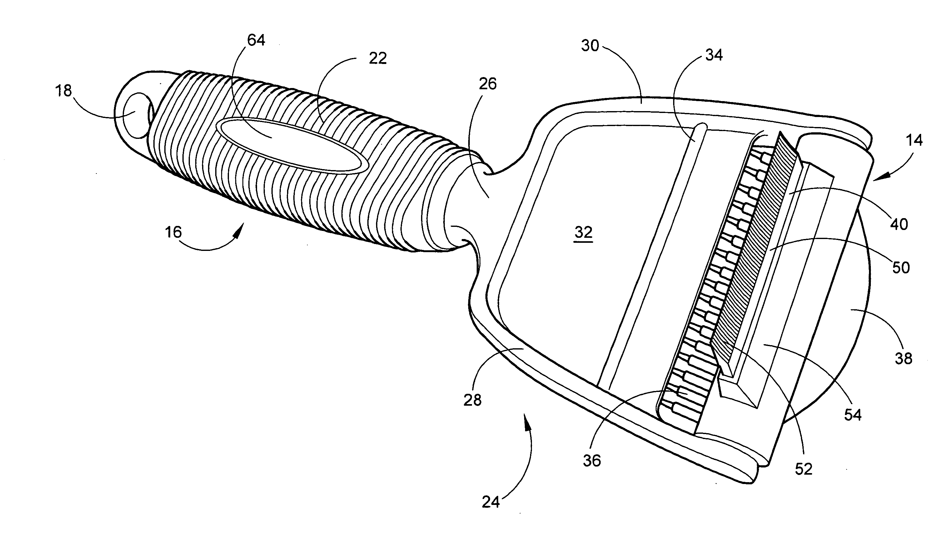
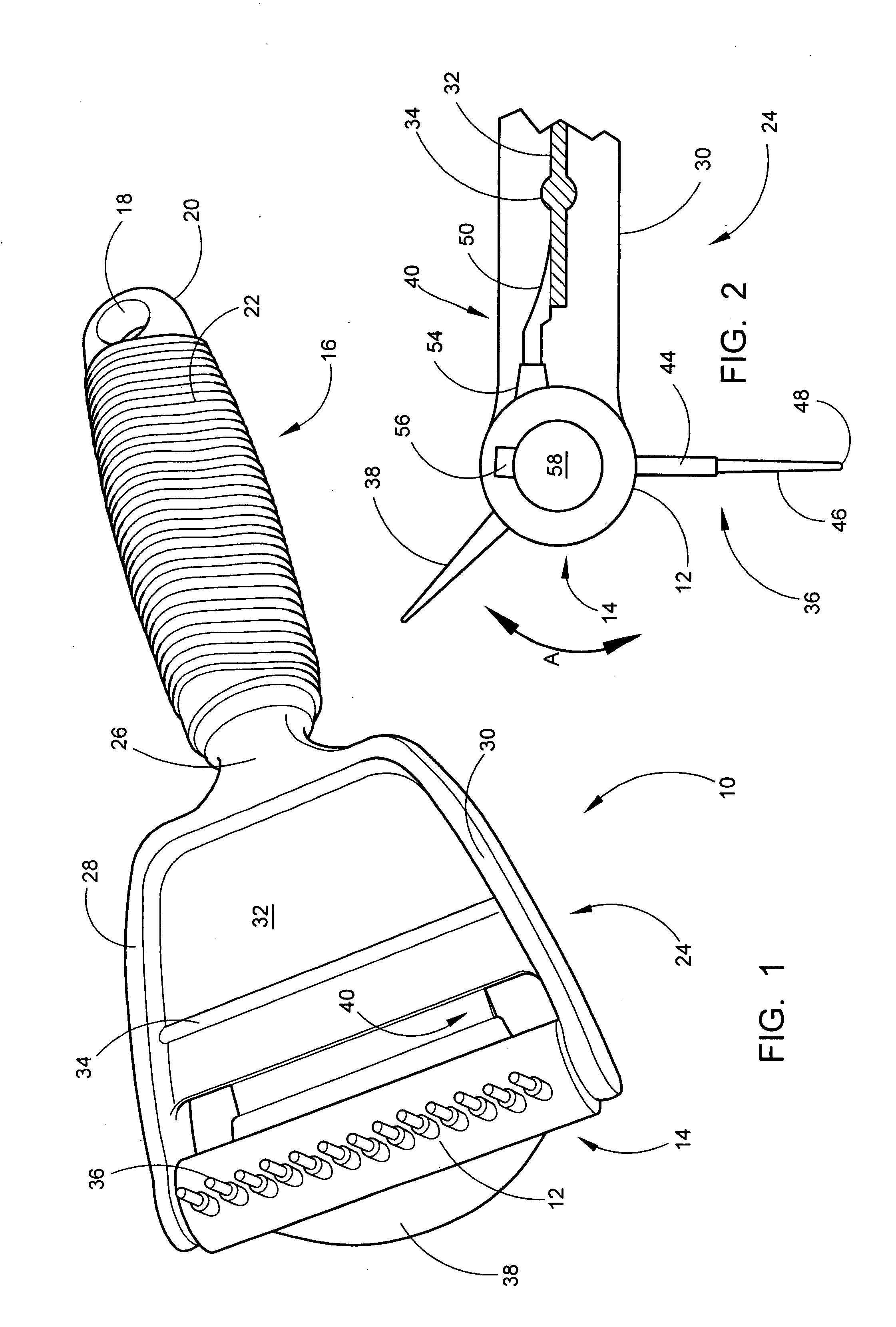
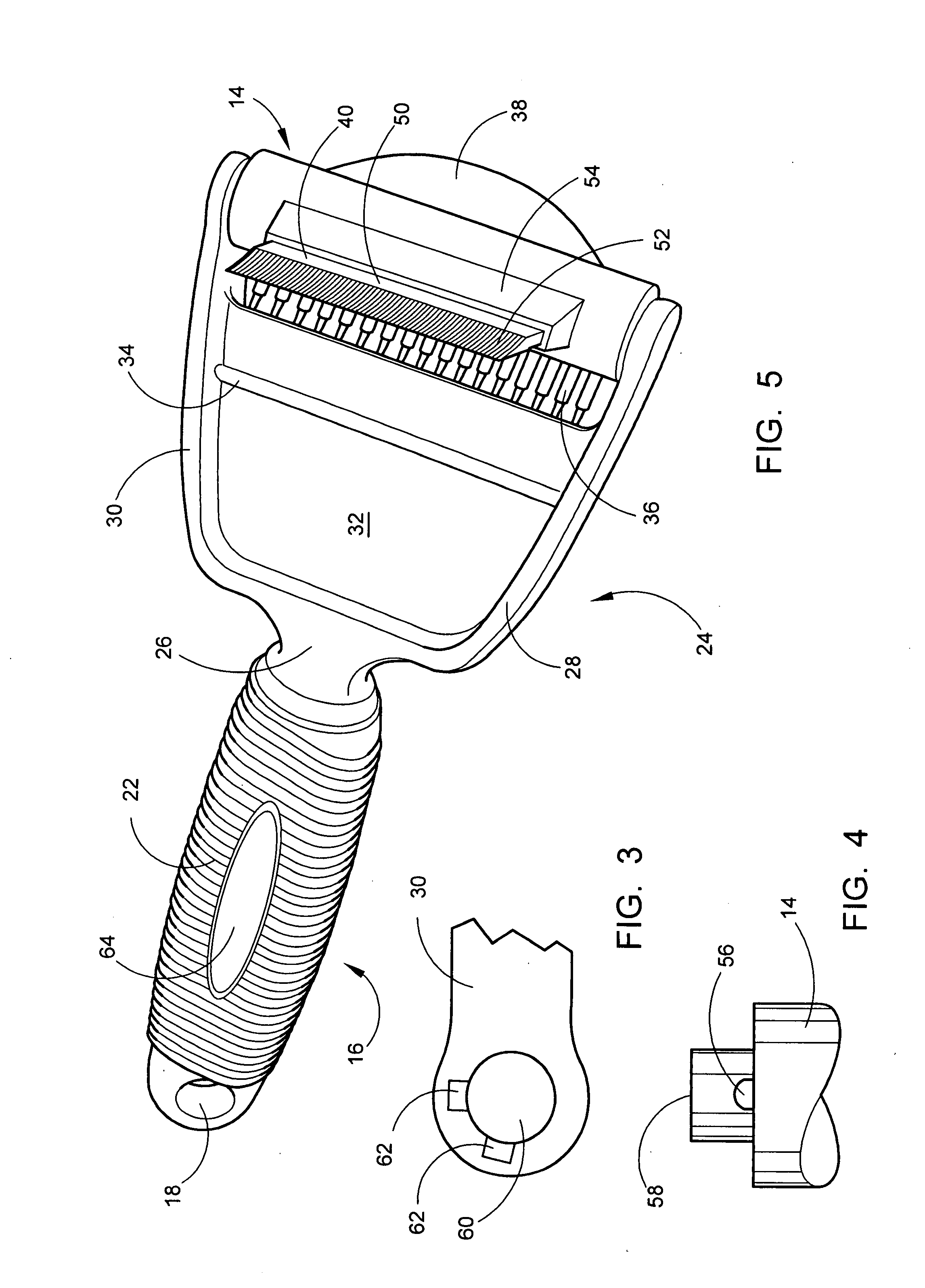
[0033]Referring now to the drawings, wherein similar parts of the present combination animal grooming tool 10 are identified by like reference numerals, there is seen in FIG. 1 a perspective view of the combination animal grooming tool 10 with the rake-brush section 12 on the rotating unit 14 exposed. The term, rake-brush has been coined by the inventor because you pull it like a rake and it accomplishes the same desired effects as a brush. The ergonomic tool handle 16 has a handle orifice 18 in the distal end 20 for hanging in a storage location. A plurality of ribs 22 extend the length of the handle 16 giving a comfortable non-slip surface.

[0034]The handle 16 connects to the tool head section 24 by the means of the tool neck 26. The tool head section 24 is composed of a first side member 28 and a second side member 30 with a supporting central web 32 between them. A strengthening rib 34 crosses between the first side member 28 and the second side member 30 on both sides of the sup...


PUM


Abstract

The present invention is directed to a combination animal grooming tool consisting of a device with a handle connected to a head with a rotating unit having two or more grooming fixtures. The first fixture is a rake-brush section consisting of a plurality of prongs and the second fixture is a de-shedding unit that is solid stainless steel tapered with a plurality of teeth spaced 0.025 inches apart. The stainless steel de-shedding unit is set into a boss on the rotating unit. An ergonomic tool handle has an orifice in the distal end for hanging in a storage location. A plurality or ribs extend the length of the handle giving a comfortable non-slip surface. The handle connects to the tool head section by the means of the tool neck. The tool head section is composed of a first side member and a second side member with a supporting central web between them. The rake-brush section of the rotating unit has a plurality of prongs in one or more lines across the rotating unit. A thumb tab is located between the rake brush section and the de-shedding unit to press on, moving the rotating unit back and forth for the desired grooming operation. The rotating unit incorporates a unique locking mechanism that restrains the unit in either the rake-brush position or the de-shedding position.

Description

[0001]This patent application claims the benefit of US provisional patent application Ser. No. 60 / 845,848 filed on Sep. 20, 2006.FIELD OF THE INVENTION[0002]This invention relates to a combination tool specifically designed for the purpose of brushing and removing the undercoat of a variety of animals. During the spring and summer months animals have the tendency of shedding their winter undercoat. Animals such dogs and cats which are kept indoors during this time will drop a great deal of loose hair within the house of the pet owner and also have the tendency to become overheated due to the accumulation of matted hair within their coat. This is why occasional grooming is essential to keep a pet happy and healthy.BACKGROUND OF THE INVENTION[0003]A wide variety of animal grooming tools are on the market, primarily sold in the pet stores to be used for grooming of dogs and cats, but it must be understood a great many of other domestic animals have the problem of shedding the winter un...

Claims


Application Information

Patent Timeline
IPC IPC(8): A01K13/00
CPCA01K13/002
Inventor ROSEN, LEON D.
Owner ROSEN LEON D
Learn More