
Water tank and method for manufacturing a water tank

a technology for water tanks and water tanks, applied in the field of water tanks, can solve the problems of high cost of water tanks, difficult assembly, and limited use of quick connectors, and achieve the effect of reducing the transport weight of monolithic water tanks and creating an aesthetically attractive appearan

Inactive Publication Date: 2008-03-20
GRAF PLASTICS A GERMAN CORP
View PDF22 Cites 14 Cited by
  • Summary
  • Abstract
  • Description
  • Claims
  • Application Information

AI Technical Summary

Benefits of technology

[0006] It is an object of the invention to provide a fair cost, reliable water tank of the kind as disclosed at the beginning, which can be manufactured universally with a view to differing demands at the site of end users and to different transport conditions, and which is available in a versatile fashion.

Problems solved by technology

The quick connectors and the sealing strip contribute significantly to the cost of the water tank.
The water tank can only be assembled with the quick connectors in separable form.
This joining principle is of advantage when the halves have to be transported for long distances to the site or into foreign countries, because the halves are stacked during transport for logistic reasons, require, however, a relatively complicated assembly on site.
Manipulating the heavy halves during the assembly with a the weight of one half of e.g. 30 kg, threading the sealing strip and mounting the e.g. 24 quick connectors is time-consuming and means a significant cost factor which might negatively influence the acceptance at the site of some end users.
However, the narrow opening edges of the halves of the known water tank do not allow reliable and watertight welding.

Method used


Image

  • Water tank and method for manufacturing a water tank
  • Water tank and method for manufacturing a water tank
  • Water tank and method for manufacturing a water tank

Examples


Embodiment Construction

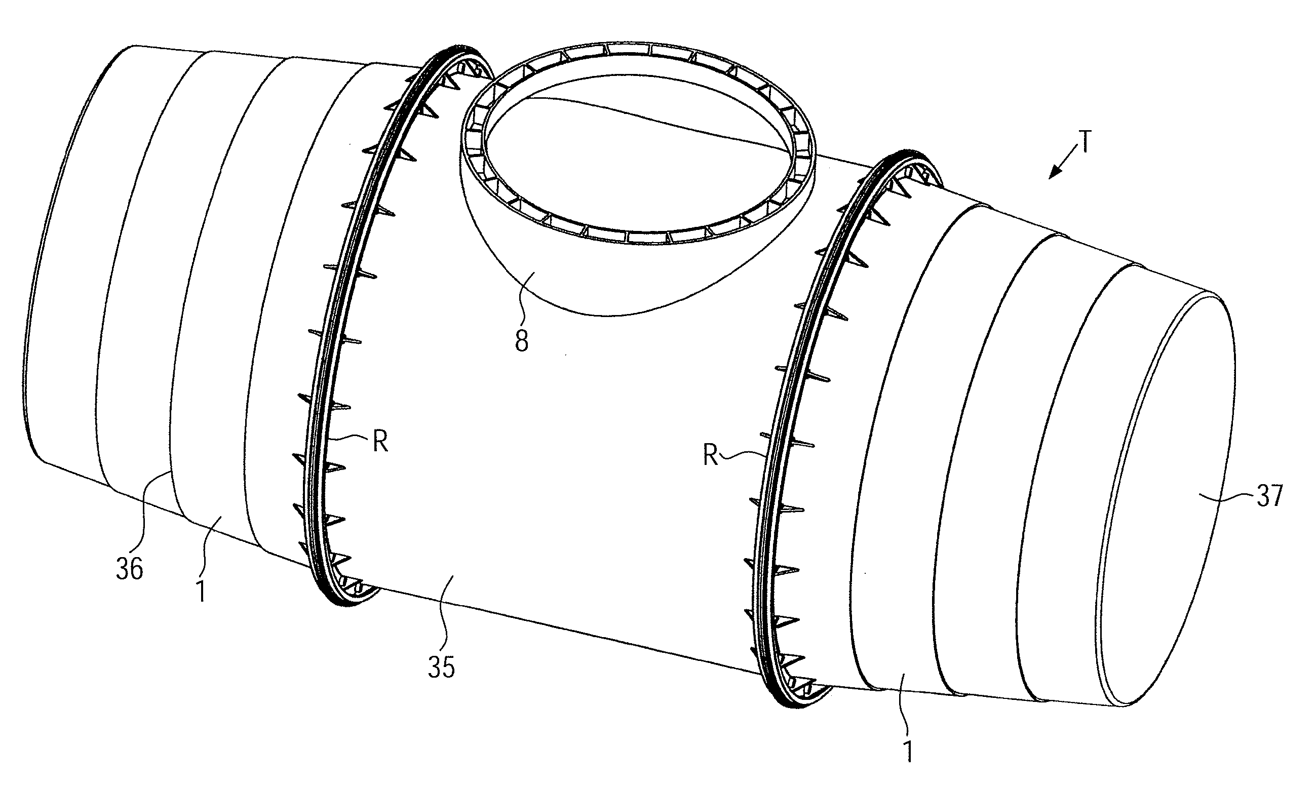
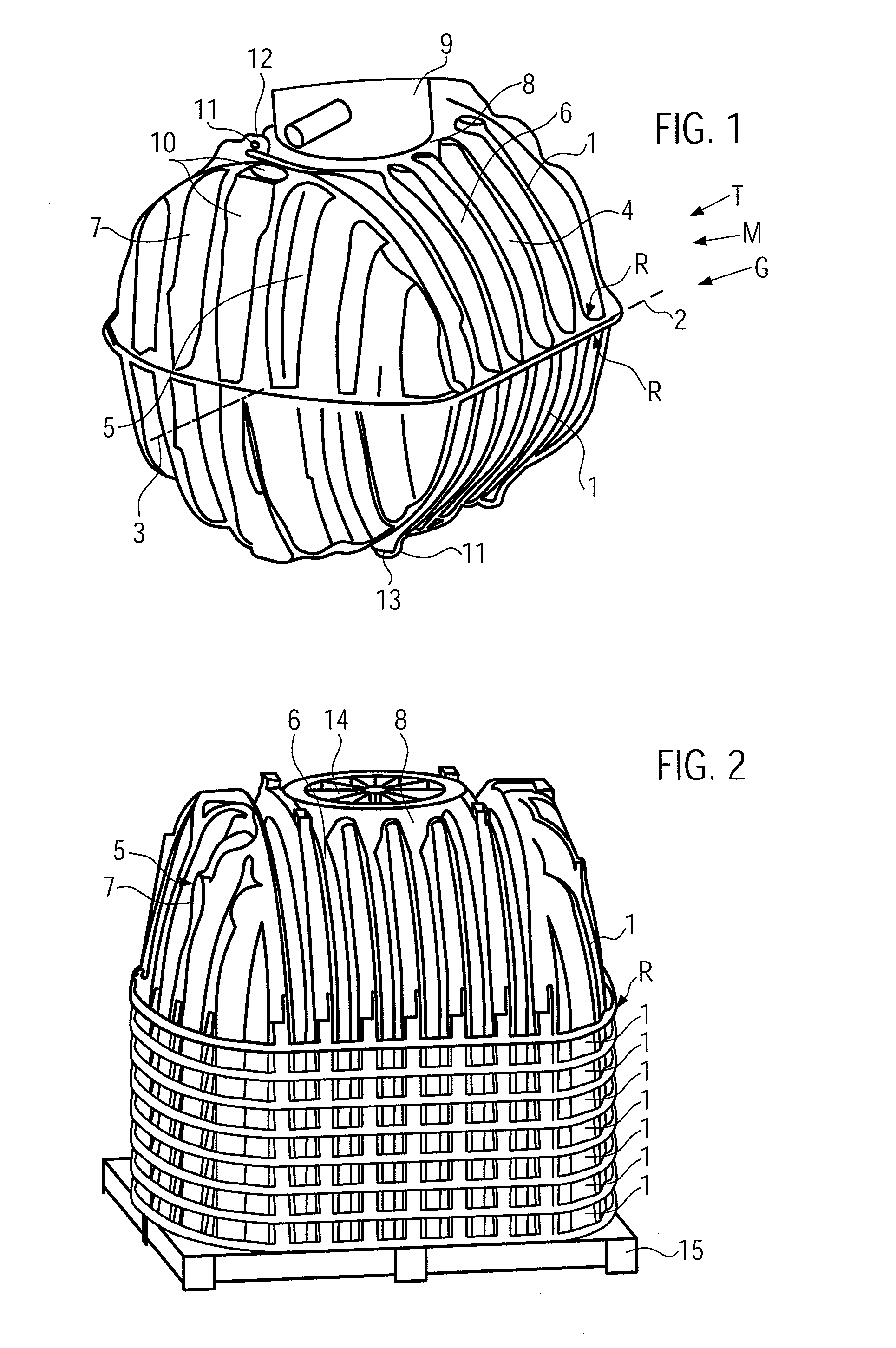
[0032] A water tank T schematically shown in FIG. 1 is assembled by joining two identical, open tank parts 1 having identical opening edge structures R. The water tank T is assembled either monolithically M, i.e. such that it cannot be separated anymore, or separable G.

[0033] In FIG. 1 the water tank T has the shape of a horizontally lying cylinder with an at least largely cylindrical contour and end caps 5 which are rounded outwardly at both cylinder ends. Ribs 6 are formed in each tank part 1 which ribs protrude inwardly, are parallel to each other, and extend substantially perpendicular to a joining plane 2 and such that the ribs 6 directly terminate in the opening edge structures R. The ribs are separated in the region of a round dome boss 8, or instead are flattened there, which dome boss 8 is formed substantially in the middle between the end caps 5. The axis of the cylinder indicated with the reference 3, consequently is situated in the joining plane 2 in which the opening e...


PUM

PropertyMeasurementUnit
weightaaaaaaaaaa
volumeaaaaaaaaaa
volumeaaaaaaaaaa

Abstract

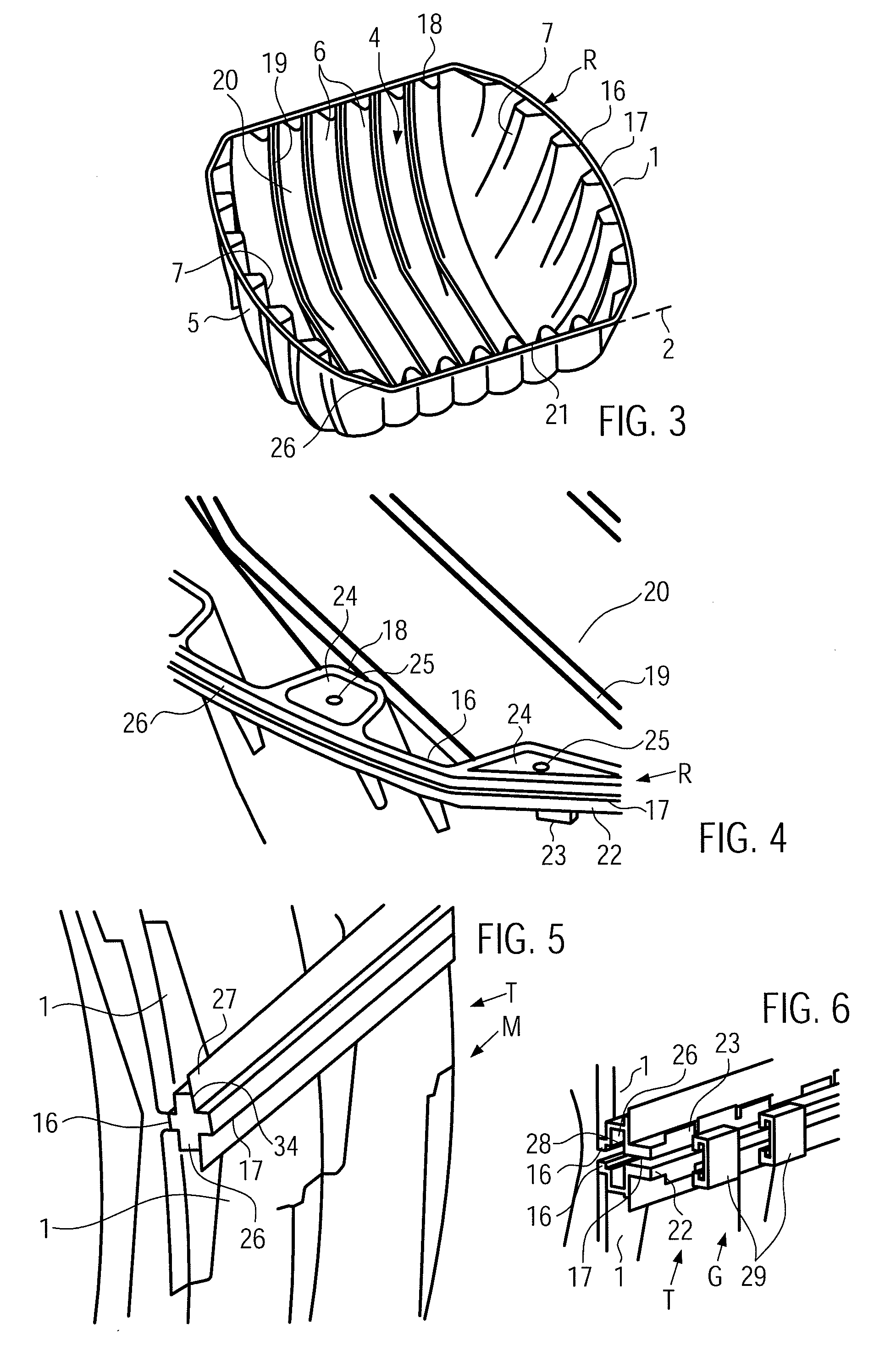
A water tank T of plastic material which is joined by using at least two open and identical tank parts 1 and a joining plane 2, the tank parts having respective opening structures R with a flattened inner opening edge, a sealing channel 26 being open towards the joining plane, and an outer flattened opening edge, the inner and outer opening edges within the opening edge structure are situated in each tank part 1, 35 in the joining plane 2, the opening edge at the same time defining inner and outer fitting surfaces 16, 17, respectively with a width exceeding the thickness X of the tank part wall 30 and the sealing channel wall 34 by at least about the half, such that the water tank T selectively can be manufactured from the same tank parts 1, 35 either monolithically by welding the fitting surfaces 16, 17 without sealing means in-between to each other or separable by clamping the opening edge structures R from the outer side with sealing means 33 provided between both tank parts 1, 35.

Description

CROSS-REFERENCE TO RELATED APPLICATIONS [0001] This application claims priority of European Patent Application No. 06018442.1, filed Sep. 4, 2006, the disclosure of which is hereby incorporated by reference in its entirety. FIELD OF THE INVENTION [0002] The invention relates to a water tank made from plastic material, which water tank is to be joined from at least two open tank parts the tank parts having opening edge structures matching each other in a joining plane each opening edge structure having a flat inner opening edge continuing a wall of the tank part a sealing receiving channel for a sealing means, the sealing receiving channel being open towards the joining plane, and an outer flat opening edge continuing wall of the sealing receiving channel, the opening edges being aligned with each other in the joining plane in joined condition of the water tank and being inner and outer fitting surfaces respectively with a width exceeding the thickness of the wall of the tank part an...

Claims


Application Information

Patent Timeline
Patent Type & Authority Applications(United States)
IPC IPC(8): B65D88/02B29C45/00B65D6/32
CPCB29C65/02B29C66/543B29C65/564B29C65/565B29C65/7802B29C65/7814B29C66/13B29C66/522B29C66/54B29C66/55B29L2024/006B29L2031/7126B29L2031/7154B65D88/025B65D88/06B65D90/004B65D90/08B29C65/562B29C65/00B29C66/8322B29C66/71B29C66/1312B29C65/7808B29K2023/12B29K2023/065
Inventor GRAF, OTTO P.
Owner GRAF PLASTICS A GERMAN CORP
Learn More