Trailing arm suspension

a trailing arm and suspension technology, applied in the direction of resilient suspensions, interconnection systems, vehicle springs, etc., can solve the problems of high cost, difficult package, complex system, etc., and achieve the effect of reducing the mounting structure, reducing the variation of the brake dive angle and the caster angl

Inactive Publication Date: 2008-03-20
ARVINMERITOR TECH
View PDF19 Cites 18 Cited by
  • Summary
  • Abstract
  • Description
  • Claims
  • Application Information

AI Technical Summary

Benefits of technology

[0006]A vehicle suspension includes a pair of trailing arms that cooperate with a Panhard arm to provide desired fore / aft and lateral stiffness. Each trailing arm includes a first end with a pivot mount for attachment to a suspension rail, a second end with an air spring support formed with the trailing arm, and an axle mount portion for attachment to an axle beam. A Panhard arm provides lateral stiffness and includes a first pivotal connection to one trailing arm and a second pivotal connection to another suspension rail laterally spaced from the one trailing arm.
[0009]In one example, the air spring support of each trailing arm includes a first support for supporting a first air spring and a second support for supporting a second air spring. The first and second air springs are longitudinally spaced apart from each other. In one configuration, the first air spring is positioned at an associated wheel center and the second air spring is spaced from the first air spring in a rearward direction. The trailing arm of the present invention comprises a light-weight arm with reduced mounting structure, and which counteracts brake wind-up and reduces brake dive and caster angle variation.
[0010]In one example, the air spring support of each trailing arm comprises an air spring platform integrally formed with the trailing arm. This allows the air spring to be directly supported by the trailing arm, with no additional components needed to provide the benefit of a significantly simplified setup with reduced maintenance requirements. Further, a clamp group for axle attachment is also significantly simplified with the use of an integrated mounting boss as discussed above.

Problems solved by technology

The independent front suspension has good ride and handling performance, however, this type of suspension is complex, heavy, difficult to package in a truck, and is cost prohibitive.
However, this type of system is also heavy, complex, and expensive.
Trailing arm air suspensions offer a reasonable compromise between cost and performance, however, these suspensions can exhibit excessive brake dive.
Excessive brake dive can cause the suspension to hit bump stops during severe braking applications.
Repeated contact between suspension components and the bump stops can adversely affect suspension performance and the overall wear life of the suspensions components.

Method used


Image

  • Trailing arm suspension
  • Trailing arm suspension
  • Trailing arm suspension

Examples


Embodiment Construction

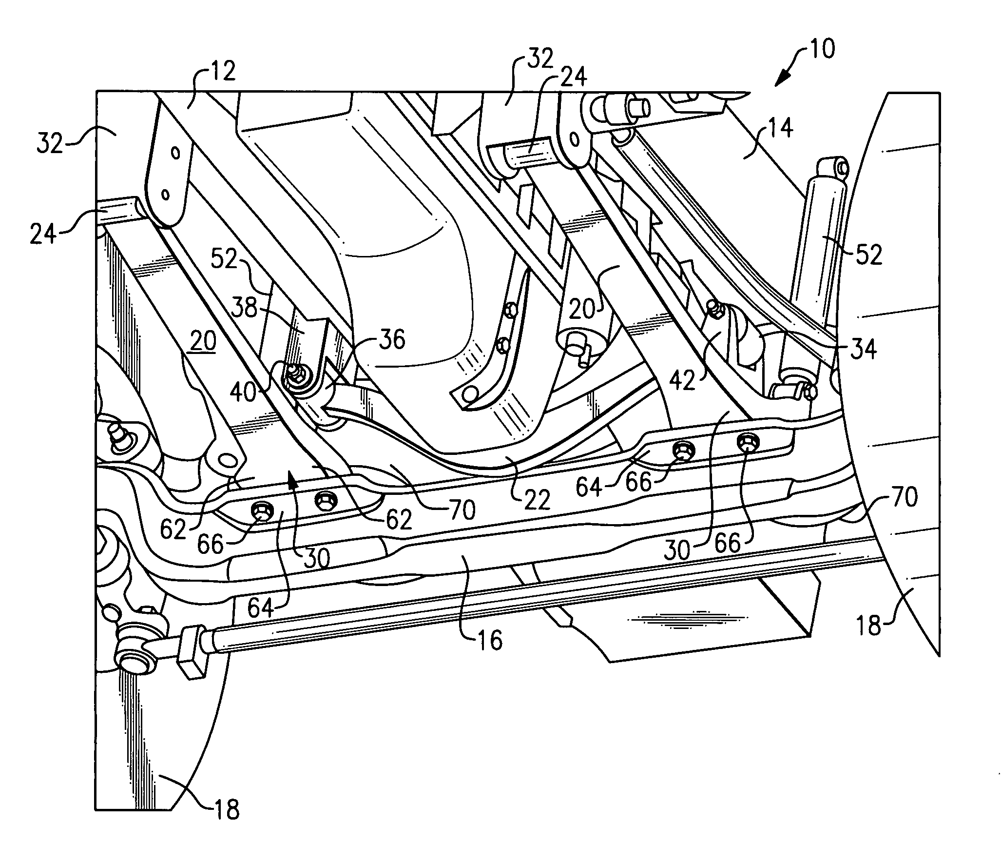
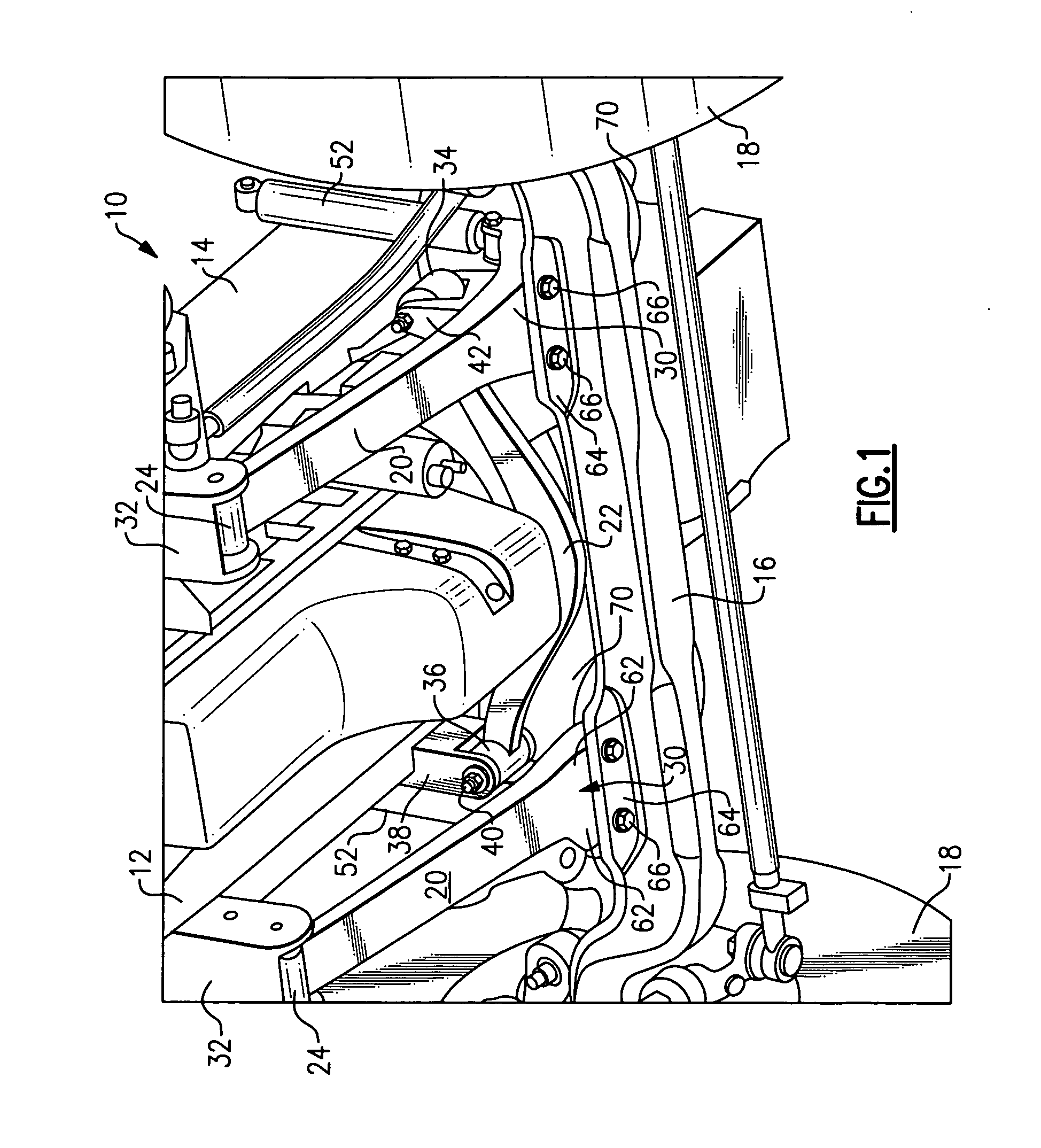
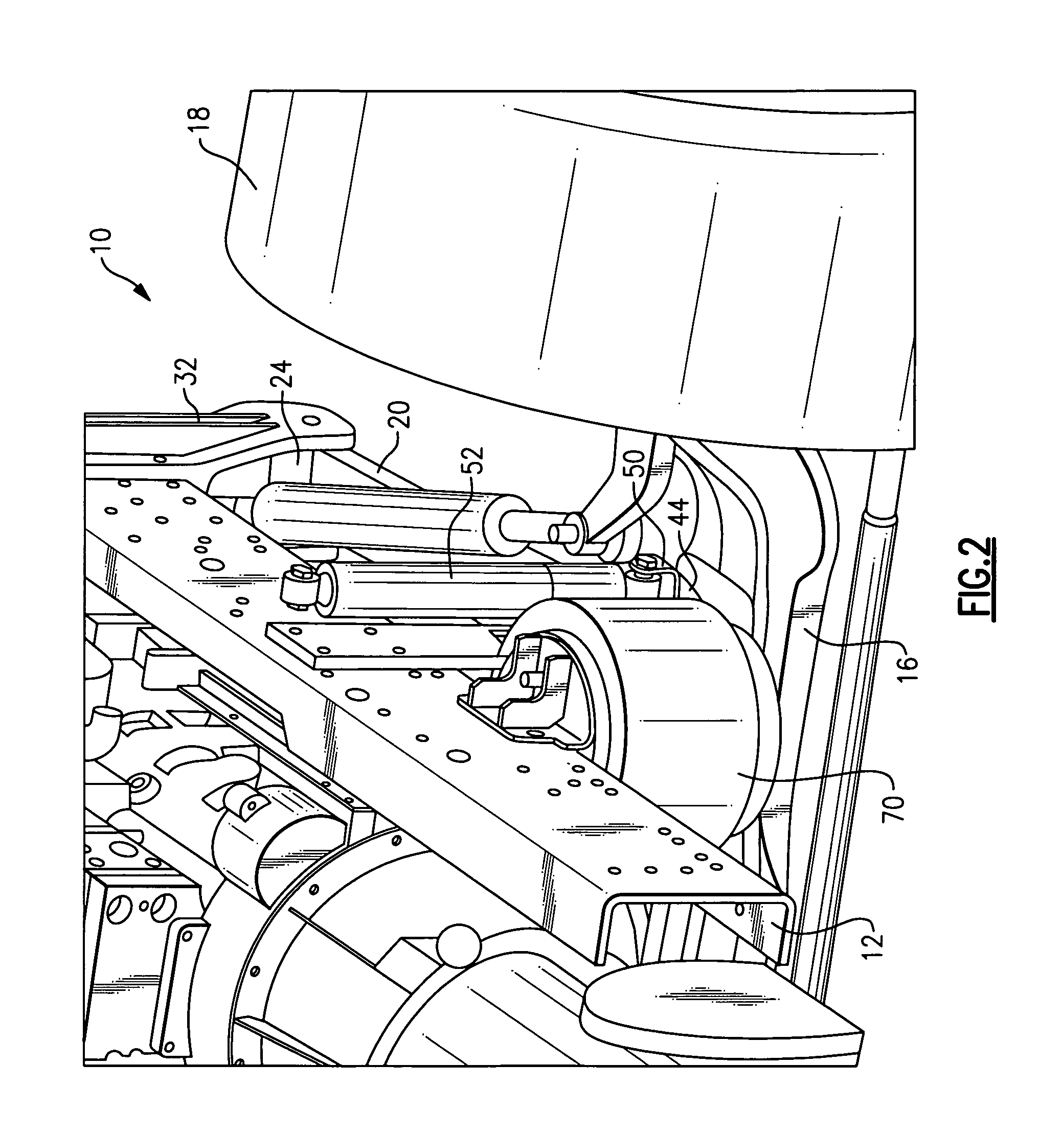
[0018]A trailing arm suspension 10 for a heavy duty vehicle is shown in FIG. 1. A first frame member 12 extends in a longitudinal direction along a vehicle length. A second frame member 14 is laterally spaced from the first frame member 12 and also extends along the longitudinal direction. The first 12 and second 14 frame members are also referred to as frame rails.

[0019]An axle beam 16 extends between laterally spaced wheels 18 that rotate about an axis of rotation that extends in a lateral direction. The axle beam 16 is used in a front non-drive steer axle configuration, however, the subject suspension 10 could also be utilized with other types of axles. The trailing arm suspension 10 connects the axle beam 16 to the first 12 and second 14 frame members.

[0020]The trailing arm suspension 10 includes a pair of trailing arms 20 that cooperate with a Panhard arm 22 to provide desired fore / aft and lateral stiffness for improved ride and handling performance. The trailing arms 20 are se...


PUM


Abstract

A vehicle suspension includes trailing arm assemblies that have one end pivotally mounted to a first suspension rail, an opposite end with an air spring support formed with the trailing arm, and an axle mount portion that is mounted to an axle beam. A Panhard arm provides lateral stiffness and includes a first pivotal connection to the trailing arm and a second pivotal connection to a second suspension rail laterally spaced from the first suspension rail.

Description

TECHNICAL FIELD[0001]The subject invention relates to a lightweight trailing arm for a vehicle suspension.BACKGROUND OF THE INVENTION[0002]The heavy duty trucking industry is seeking alternative suspension system solutions that offer a better ride performance than-conventional mechanical leaf suspensions, while maintaining or improving handling performance. Light to medium heavy suspensions, i.e. suspensions for up to approximately 14,000 pounds, have utilized air suspension configurations that provide improved ride performance, but which have marginal handling performance.[0003]One solution for heavy front suspensions, i.e. suspensions for up to approximately 20,000-23,000 pounds, is the use of an independent front suspension. The independent front suspension has good ride and handling performance, however, this type of suspension is complex, heavy, difficult to package in a truck, and is cost prohibitive. Another solution utilizes a multi-link air suspension, which provides good r...

Claims


Application Information

Patent Timeline
Patent Type & Authority Applications(United States)
IPC IPC(8): B60G9/00B60G21/05
CPCB60G7/001B60G9/003B60G11/27B60G2300/026B60G2200/341B60G2202/152B60G2204/14B60G2200/31
Inventor VARELA, TOMAZ DOPICOWEN, XINYUYANG, KOULEDESMA, RAGNAR H.
Owner ARVINMERITOR TECH
Why Eureka
Try Eureka