Re-entrant resonant cavities and method of manufacturing such cavities

Inactive Publication Date: 2008-03-20
ALCATEL LUCENT SAS
View PDF14 Cites 6 Cited by
  • Summary
  • Abstract
  • Description
  • Claims
  • Application Information

AI Technical Summary

Benefits of technology

[0015]According to another aspect of the invention, a filter arrangement includes a plurality of re-entrant resonant cavities, at least one of which comprises: an electrically conductive surface defining a volume and including a re-entrant stub having an end face and a longitudinal axis, there being a capacitive gap between the end face and a facing portion of the surface, the configurations of the stub and the facing portion being such that

Problems solved by technology

If milling is used to shape the plastic, it can be difficult to achieve sufficient accuracy, and surface roughness may be an issue.
Molding is another approach, but the tooling is

Method used


Image

  • Re-entrant resonant cavities and method of manufacturing such cavities
  • Re-entrant resonant cavities and method of manufacturing such cavities
  • Re-entrant resonant cavities and method of manufacturing such cavities

Examples


Embodiment Construction

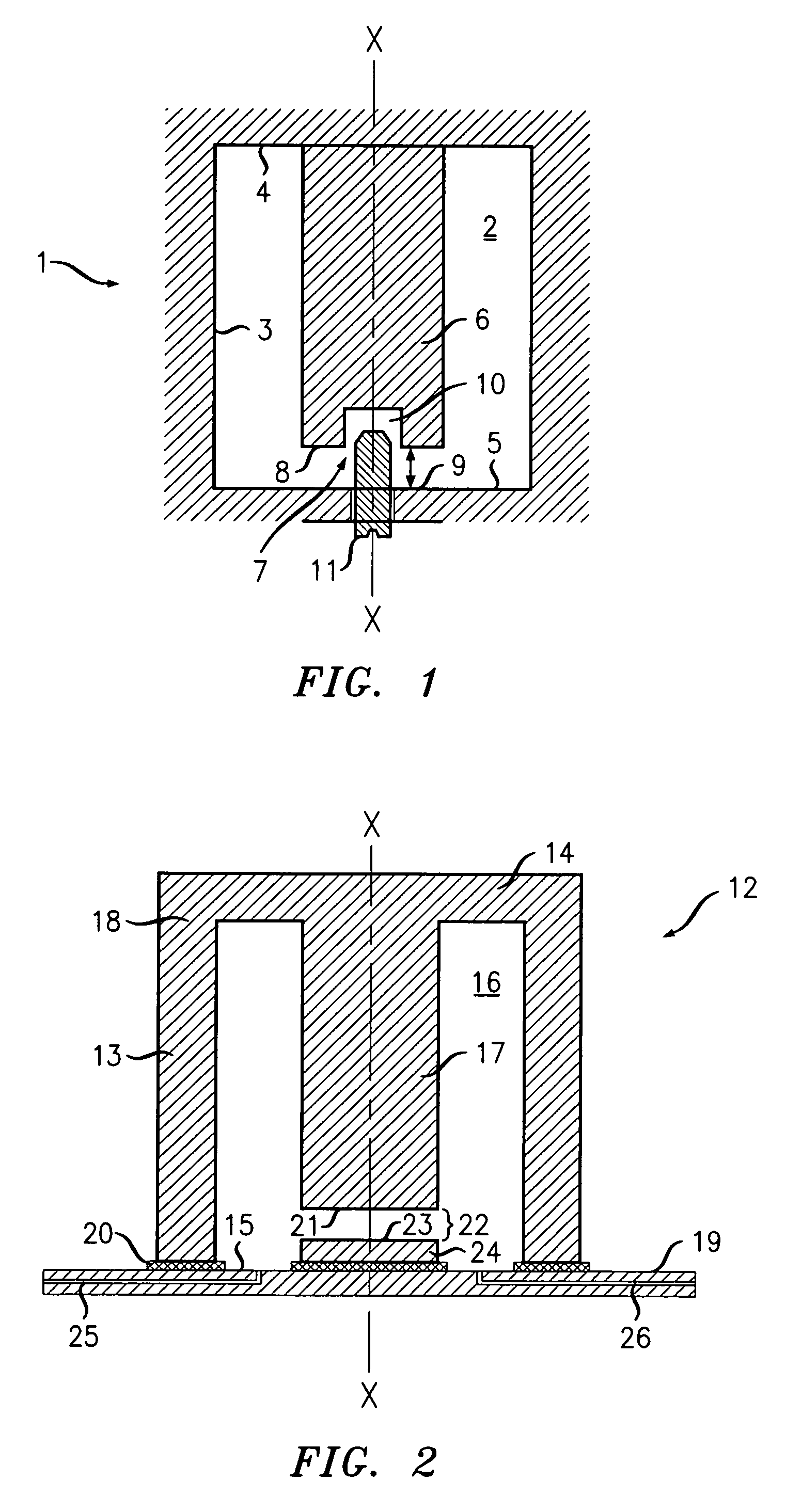
[0023]With reference to FIG. 2, a re-entrant microwave resonant cavity 12 comprises a cylindrical wall 13, with first and second end walls 14 and 15 respectively at each end to define a volume 16 between them. A stub 17 is extensive from the first end wall 14 into the volume 16, being located along the longitudinal axis X-X of the cylindrical wall 13. The cylindrical wall 13, first end wall 14 and stub 17 are integrally formed as a single molded plastic component 18, the interior surface of which is metallized with a layer of silver. The second end wall 15 is defined by a metallization layer carried by a printed circuit board substrate 19. The cylindrical wall 13 is joined to the metallization layer by solder 20 laid down in a surface mount soldering process during fabrication of the device.

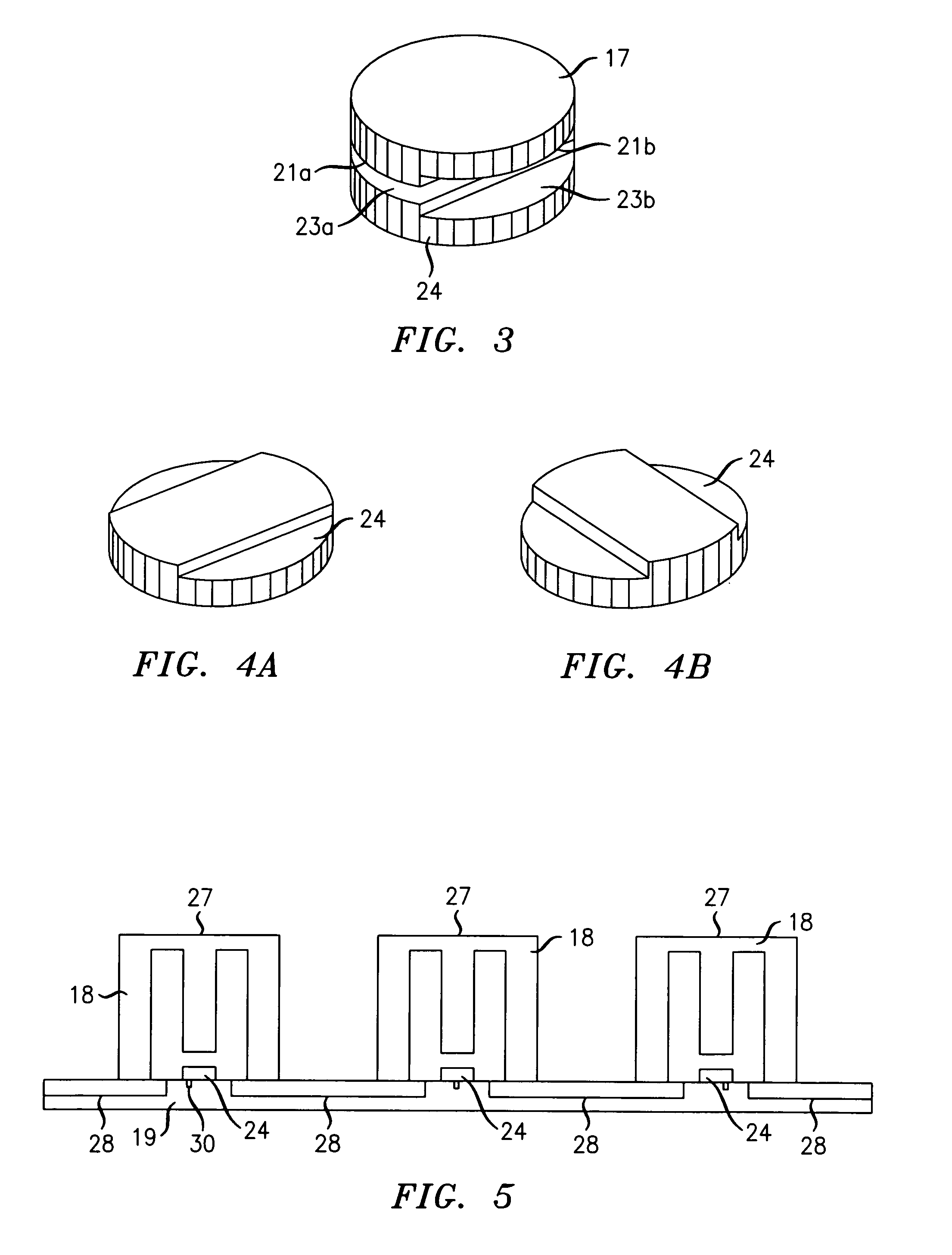
[0024]The end face 21 of the stub 17 defines a gap 22 between it and the facing portion 23 of the second end wall 15. The facing portion 23 of the second end wall 15 is formed by a rostrum 24, wh...


PUM

PropertyMeasurementUnit
Fractionaaaaaaaaaa
Volumeaaaaaaaaaa
Frequencyaaaaaaaaaa

Abstract

A re-entrant resonant cavity 12 includes a first metallized molded plastic component 18, which comprises a re-entrant stub 17, an end wall 14 and a cylindrical side wall 13. The component 18 is surface mount soldered to a metallized PCB substrate 19. A rostrum 24 is located facing the end face 21 of the stub 17 to define a capacitive gap 22 with it.
The end face 21 of the stub 17 and the rostrum 24 are configured such that relative rotation between them changes the profile of the gap 22 and hence the gap capacitance. By suitably locating the two parts during manufacture, a particular capacitance may be chosen to give a desired resonance frequency from a selection available depending on the relative angular position of the stub 17 and rostrum 24.
In another cavity, the rostrum is replaced by an etched metallization layer of a printed circuit board.

Description

FIELD OF THE INVENTION[0001]The present invention relates to re-entrant resonant cavities and to a method of manufacturing such cavities. More particularly, but not exclusively, it relates to re-entrant cavities manufactured using surface mount techniques and to multi-resonator filter arrangements.BACKGROUND OF THE INVENTION[0002]A resonant cavity is a device having an enclosed volume bounded by electrically conductive surfaces and in which oscillating electromagnetic fields are sustainable. Resonant cavities may be used filters, for example, and have excellent power handling capability and low energy losses. Several resonant cavities may be coupled together to achieve sophisticated frequency selective behavior.[0003]Resonant cavities are often milled in, or cast from, metal. The frequency of operation determines the size of the cavity required, and, in the microwave range, the size and weight are significant. In a re-entrant resonant cavity, the electric and magnetic parts of the e...

Claims


Application Information

Patent Timeline
IPC IPC(8): H05B41/24H05B41/16H05K3/20
CPCH01P7/04H01P11/007Y10T29/49155Y10T29/49128H01P11/008H01P11/00
Inventor HESSELBARTH, JAN
Owner ALCATEL LUCENT SAS
Why Eureka
Try Eureka