
Frequency divider and method for controlling the same

a frequency divider and frequency technology, applied in the field of frequency dividers, can solve the problems of increasing costs and and achieve the effect of increasing the size of the circuit configuration

Inactive Publication Date: 2008-03-20
PANASONIC CORP
View PDF7 Cites 4 Cited by
  • Summary
  • Abstract
  • Description
  • Claims
  • Application Information

AI Technical Summary

Benefits of technology

[0021] This results in the need for a plurality of frequency dividing circuits the number of which is equal to or greater than that of the output frequency dividing ratios, increasing costs and the size of the circuit configuration.
[0022] The present invention solves the above conventional problems. An object of the present invention is to provide a frequency divider that can output a plurality of different frequency dividing signals using a configuration having a reduced number of frequency dividing circuits, as well as a method for controlling the frequency divider.
[0047] The present invention can provide a frequency divider that can output a plurality of different frequency dividing signals using a configuration having a reduced number of frequency dividing circuits, as well as a method for controlling the frequency divider.

Problems solved by technology

This results in the need for a plurality of frequency dividing circuits the number of which is equal to or greater than that of the output frequency dividing ratios, increasing costs and the size of the circuit configuration.

Method used


Image

  • Frequency divider and method for controlling the same
  • Frequency divider and method for controlling the same
  • Frequency divider and method for controlling the same

Examples


embodiment 1

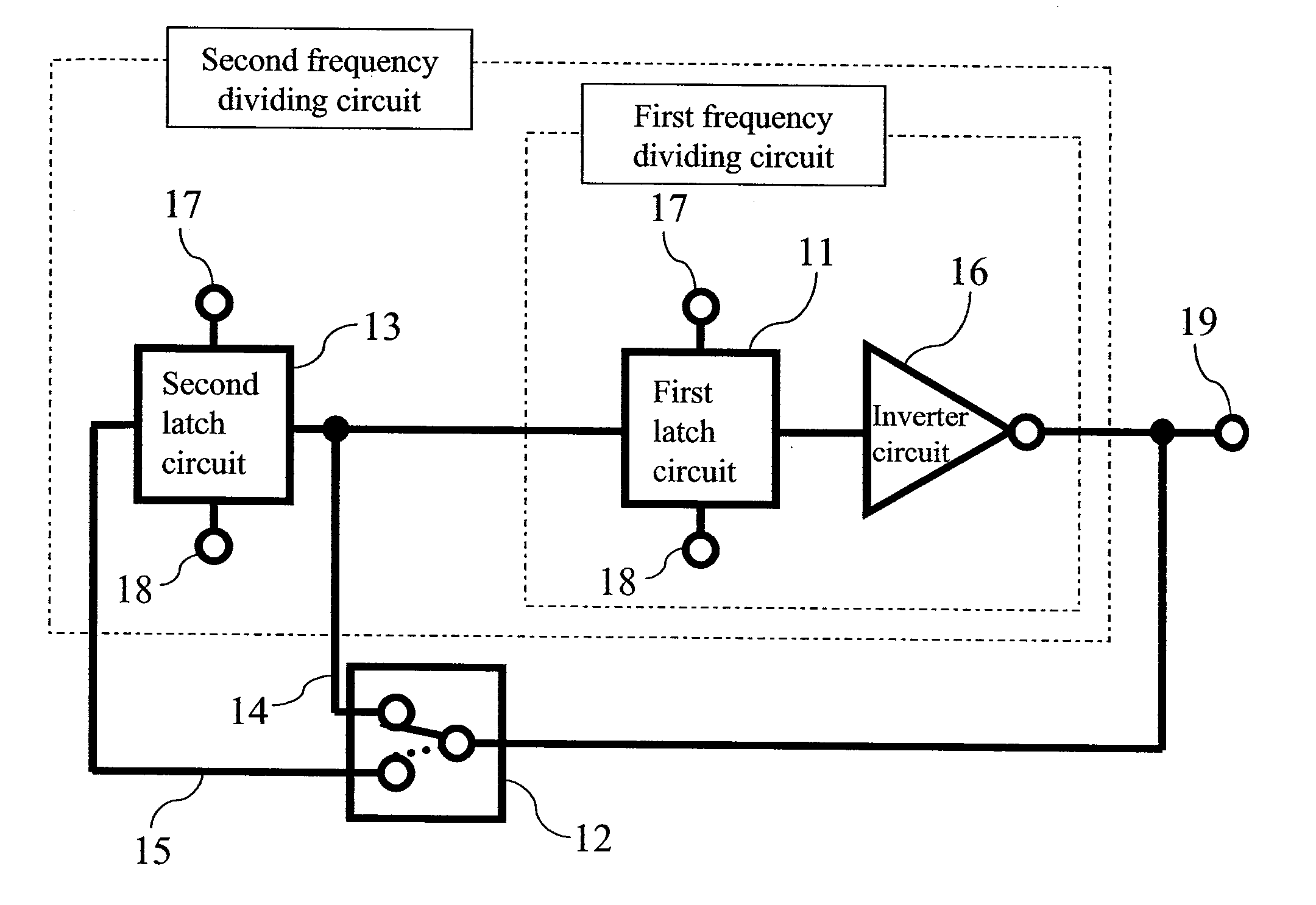
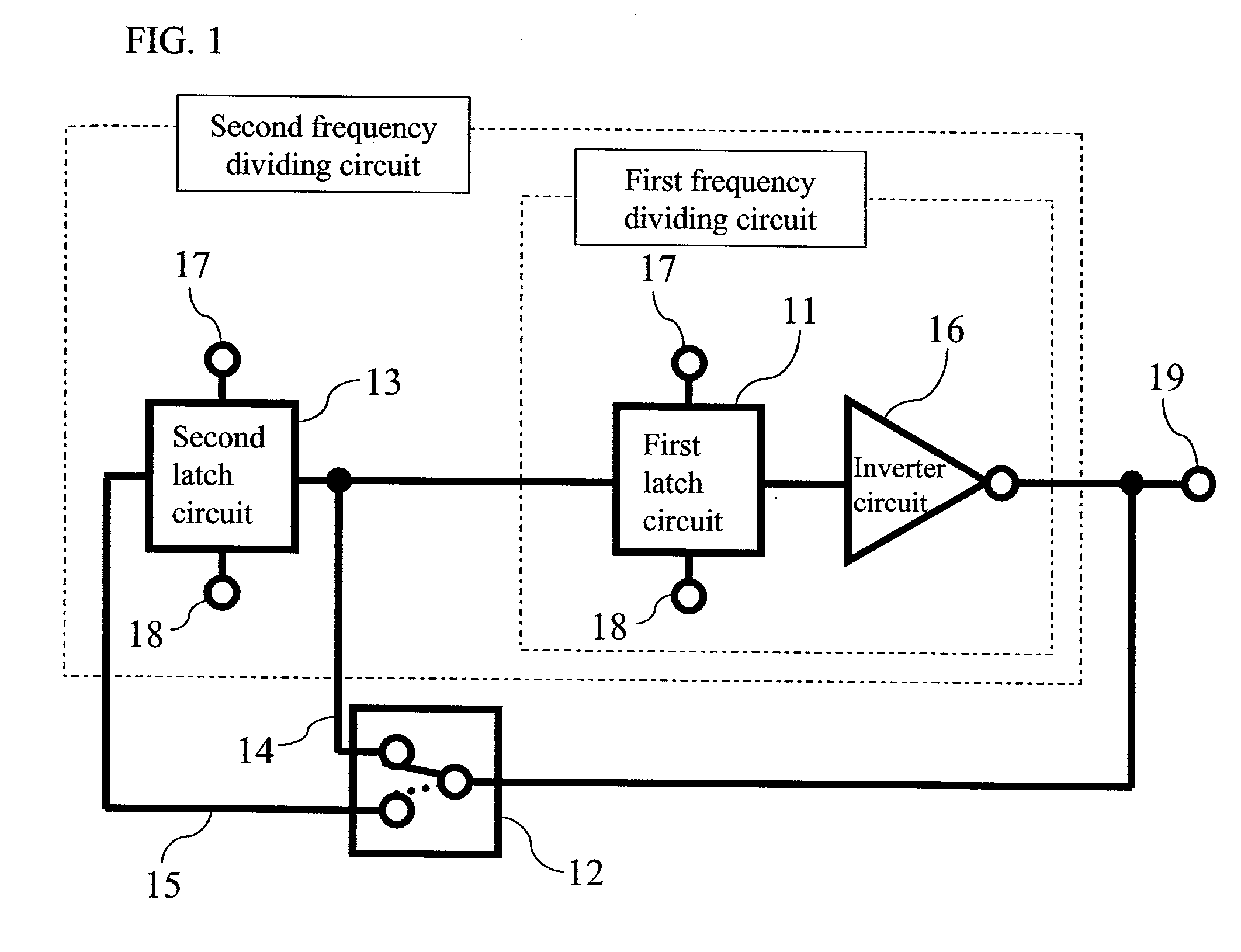
[0079]FIG. 1 shows the circuit configuration of a frequency divider in accordance with Embodiment 1 of the present invention.

[0080] The frequency divider in accordance with Embodiment 1 comprises a first latch circuit 11, a second latch circuit 13 having an output connected to an input of the first latch circuit 11, and an inverter circuit 16 connected to an output of the first latch circuit 11. Each of the first latch circuit 11 and the second latch circuit 13 has a clock input section 17 to which a clock signal is input and an inversion clock input section 18 to which an inversion clock signal is input.

[0081] An output of the inverter circuit 16 is connected to an output section 19. The frequency divider also comprises a first feedback path 14 that connects an output from the inverter circuit 16 to an input of the first latch circuit 11 and a second feedback path 15 that connects the output from the inverter circuit 16 to an input of the second latch circuit 13.

[0082] The frequ...

embodiment 2

[0103]FIG. 6 shows the circuit configuration of a frequency divider in accordance with Embodiment 2 of the present invention.

[0104] The frequency divider in accordance with Embodiment 2 comprises a first latch circuit 51, a second latch circuit 53, and an inverter circuit 57 connected to an output of the first latch circuit 51. Each of the first latch circuit 51 and the second latch circuit 53 has a clock input section 58 to which a clock signal is input and an inversion clock input section 59 to which an inversion clock signal is input.

[0105] An output of the inverter circuit 57 is connected to an output section 60. The frequency divider also comprises a first feedback path 54 that connects an output from the inverter circuit 57 to an input of the first latch circuit 51 and a second feedback path 56 that connects the output from the inverter circuit 57 to an input of the second latch circuit 53.

[0106] The frequency divider further comprises a switching circuit 52 that switches c...


PUM


Abstract

Conventional frequency dividers allowing a plurality of output signals with different frequency dividing ratios to be output require a plurality of frequency dividing circuits the number of which is equal to or greater than that of the output frequency dividing ratios. This increases the sizes and costs of the conventional frequency dividers. A frequency divider in accordance with the present invention includes a plurality of latch circuits connected together in series to which a clock signal and a clock inversion signal are input, an inverter circuit to which an output signal from a last connected one of the latch circuits is input, an output terminal to which an output from the inverter circuit is connected, and a plurality of feedback paths that connect the output from the inverter circuit to respective inputs of the plurality of latch circuits. The frequency divider further includes a switching circuit that switches connections to the plurality of feedback paths so that an output signal from the inverter circuit is input to only one of the plurality of latch circuits.

Description

BACKGROUND OF THE INVENTION [0001] 1. Field of the Invention [0002] The present invention relates to a frequency divider and a method for controlling the frequency divider. The present invention relates to a frequency divider, for example, for use in radio communication apparatuses such as cellular phones, and a method for controlling the frequency divider. [0003] 2. Related Art of the Invention [0004] In recent years, radio communication systems have been commonly used in public communications, computer networks, and the like. Further, the use of a system has been started which has a reduced number of oscillators for a reduction in the size and cost of high frequency ICs, and frequency dividers connected behind the oscillators and having different frequency dividing ratios in order to deal with a plurality of transmission frequencies. [0005] Some conventional techniques implement switching of the frequency dividing ratio by connecting a plurality of frequency division circuits in s...

Claims


Application Information

Patent Timeline
Patent Type & Authority Applications(United States)
IPC IPC(8): H03B19/00
CPCH03K23/42H03K23/66H03K23/44
Inventor SHIMADA, MIKIHIRO
Owner PANASONIC CORP
Learn More