Doherty amplifier

Inactive Publication Date: 2008-03-20
KOKUSA ELECTRIC CO LTD
View PDF3 Cites 28 Cited by
  • Summary
  • Abstract
  • Description
  • Claims
  • Application Information

AI Technical Summary

Benefits of technology

[0027]a difference calculator for calculating a difference between the maximum voltage value of the envelop held by the peak hold circuit and the voltage value detected by the average power detector; and
[0028]a

Problems solved by technology

In general, the amplification of a modulation wave signal with a high peak-to-average power ratio causes a large distortion due to a poor linearity when back-off of an amplifier is made small for improvement of efficiency thereof.
However, the ratio of input powers D and E depends upon the configuration of the amplifier, which makes it almost impossible to change the ratio using the conventional Doherty amplifier starting at around 3 dB.
Further, an output power of a transmission amplifier for amplifying these signals is not also constant due to a transmission power control and so on.
If a Doherty amplifier provided with the adaptor bias circuit is used in a certain power below an average input power, the gate bias of the peak amplifier is always set below the optimum gate bias B, thereby making it impossible to fully operate the peak amplifier when a signal having a high peak-to-average power ratio is inputted thereto.
In addition, in the case of a signal having low peak-to-average power ratio, it is not possible to fully operate the peak amplifier.

Method used


Image

  • Doherty amplifier
  • Doherty amplifier
  • Doherty amplifier

Examples


Embodiment Construction

[0044]Hereinafter, embodiments of the present invention will be described in detail with reference to the accompanying drawings.

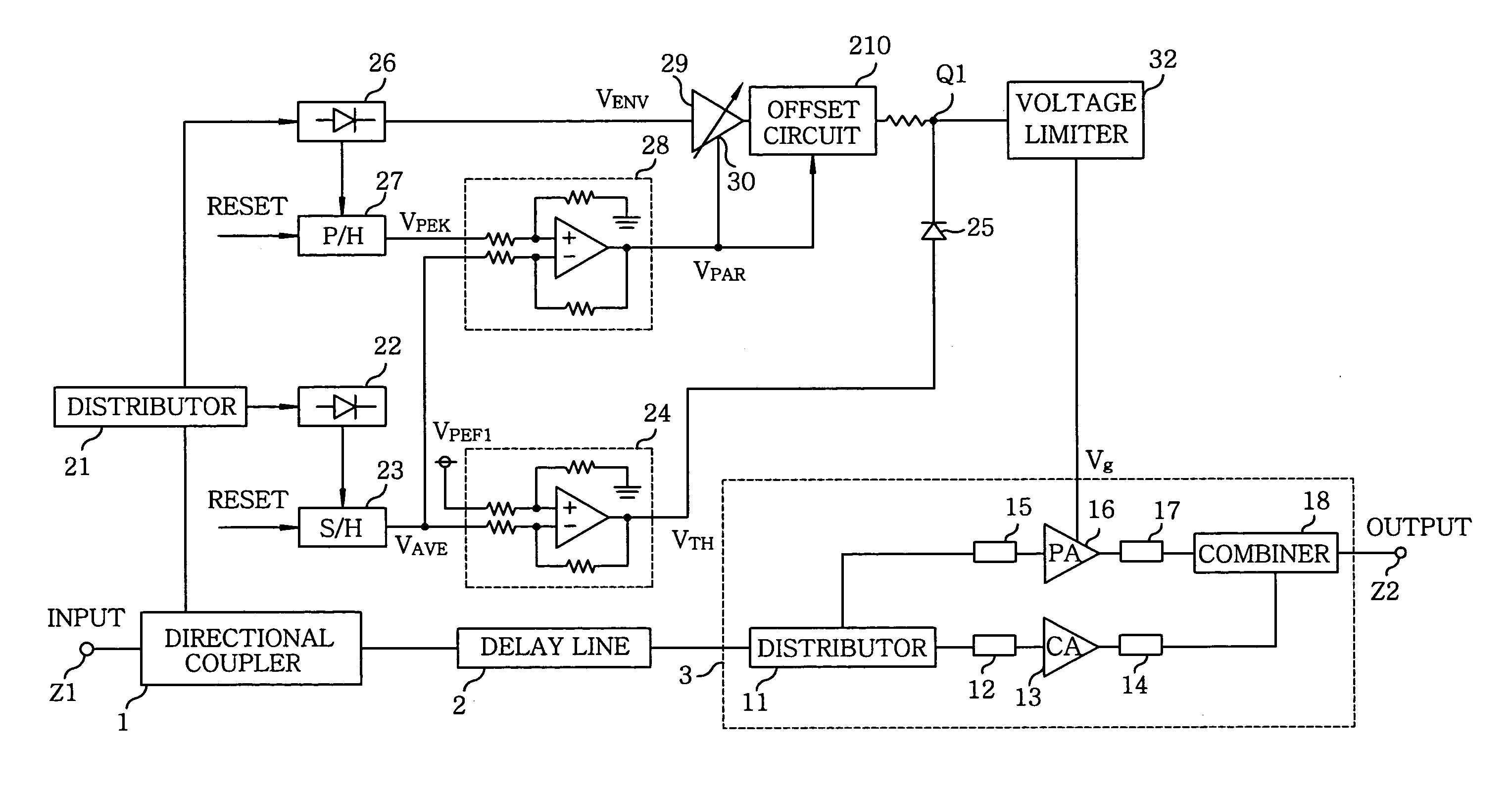
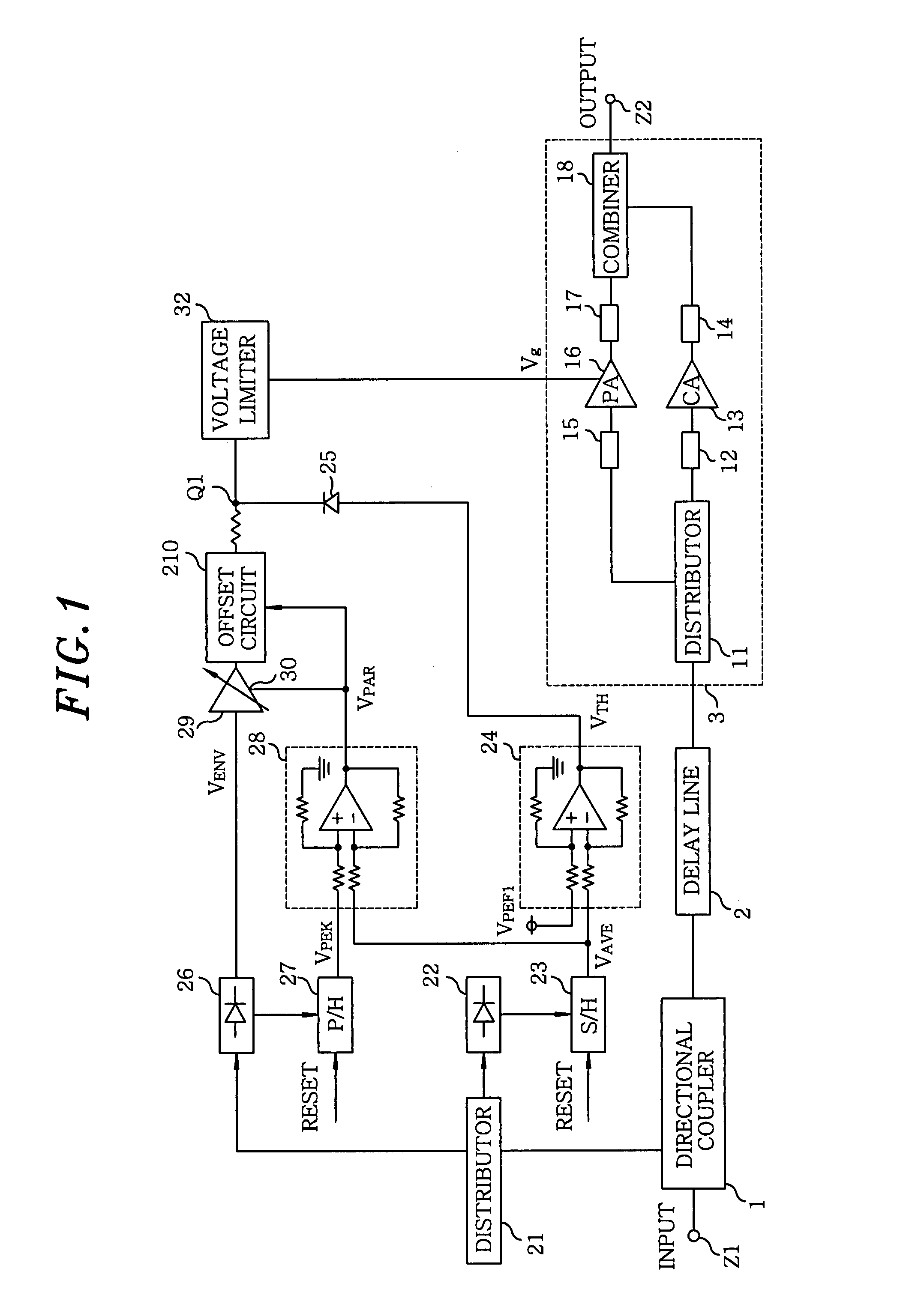
[0045]Referring to FIG. 1, there is shown an exemplary configuration of a Doherty amplifier having an active bias circuit in accordance with an embodiment of the present invention.

[0046]The Doherty amplifier of this embodiment includes a directional coupler 1, a delay line 2, and a Doherty amplification circuit (a part of main body of the Doherty amplifier) 3, which are arranged between an input terminal Z1 and an output terminal Z2. The Doherty amplification circuit 3 is provided with a distributor 11, a transmission line 12 for delay, a carrier amplifier (CA) 13, a transmission line 14 having an electric length of θ+90°, a transmission line 15 for delay, a peak amplifier (PA) 16, a transmission line 17 having an electric length of Φ, and a combiner 18.

[0047]In addition, the Doherty amplifier of this embodiment includes a distributor 21, an average power d...


PUM


Abstract

A Doherty amplifier includes a Doherty amplification circuit and an active bias circuit. The active bias circuit includes an average power detector for detecting a value of a voltage representing an average power of an input signal, an envelop detector for detecting an envelop of the input signal, a threshold calculator for calculating a boundary value of the envelop detected by the envelop detector based on the value of the voltage detected by the average power detector, and a voltage limiter for limiting the envelop detected by the envelop detector below a predetermined value. The bias voltage corresponding to the average power of the input signal is applied to the Doherty amplification circuit.

Description

FIELD OF THE INVENTION[0001]The present invention relates to a Doherty amplifier; and, more particularly, to a Doherty amplifier for controlling biases properly.BACKGROUND OF THE INVENTION[0002]In general, the amplification of a modulation wave signal with a high peak-to-average power ratio causes a large distortion due to a poor linearity when back-off of an amplifier is made small for improvement of efficiency thereof. On the contrary, when the back-off is made large for improvement of the linearity, the efficiency is lowered. For example, a Doherty amplifier is provided as a method for improving the efficiency with the same back-off.[0003]FIG. 9 shows a configuration of a conventional Doherty amplification circuit. The conventional Doherty amplification circuit includes a distributor 113 for dividing an input signal into two signals; a class AB or B carrier amplifier 111, a class C peak amplifier 112; a mixer 114 for combining an output signal from the carrier amplifier with an o...

Claims


Application Information

Patent Timeline
IPC IPC(8): H03F3/68
CPCH03F1/0261H03F1/0288H03F2200/375H03F2200/102H03F2200/18H03F1/52
Inventor IWASAKI, TAKASHI
Owner KOKUSA ELECTRIC CO LTD
Why Eureka
Try Eureka