Power Control in a Local Network Node (Lln)

a power control and local network technology, applied in the field of communication system, can solve problems such as the degradation of the coverage of the macro-cell

Active Publication Date: 2008-03-20
COMMSCOPE TECH LLC
View PDF99 Cites 262 Cited by
  • Summary
  • Abstract
  • Description
  • Claims
  • Application Information

AI Technical Summary

Problems solved by technology

In this arrangement, the downlink transmissions from the pico-cell will interfere with the downlink transmissions from the macro-cell, and the interference is likely to result in degradation in the coverage of the macro-cell.

Method used


Image

  • Power Control in a Local Network Node (Lln)
  • Power Control in a Local Network Node (Lln)
  • Power Control in a Local Network Node (Lln)

Examples


Embodiment Construction

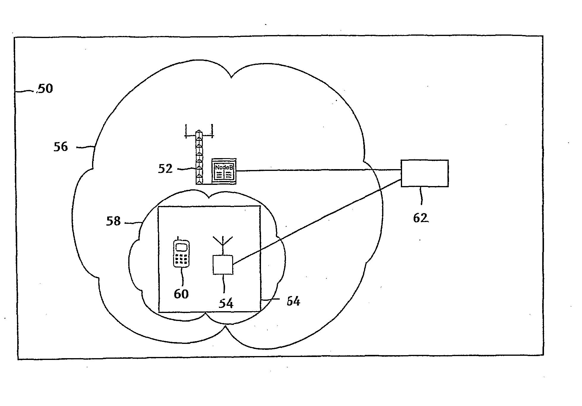
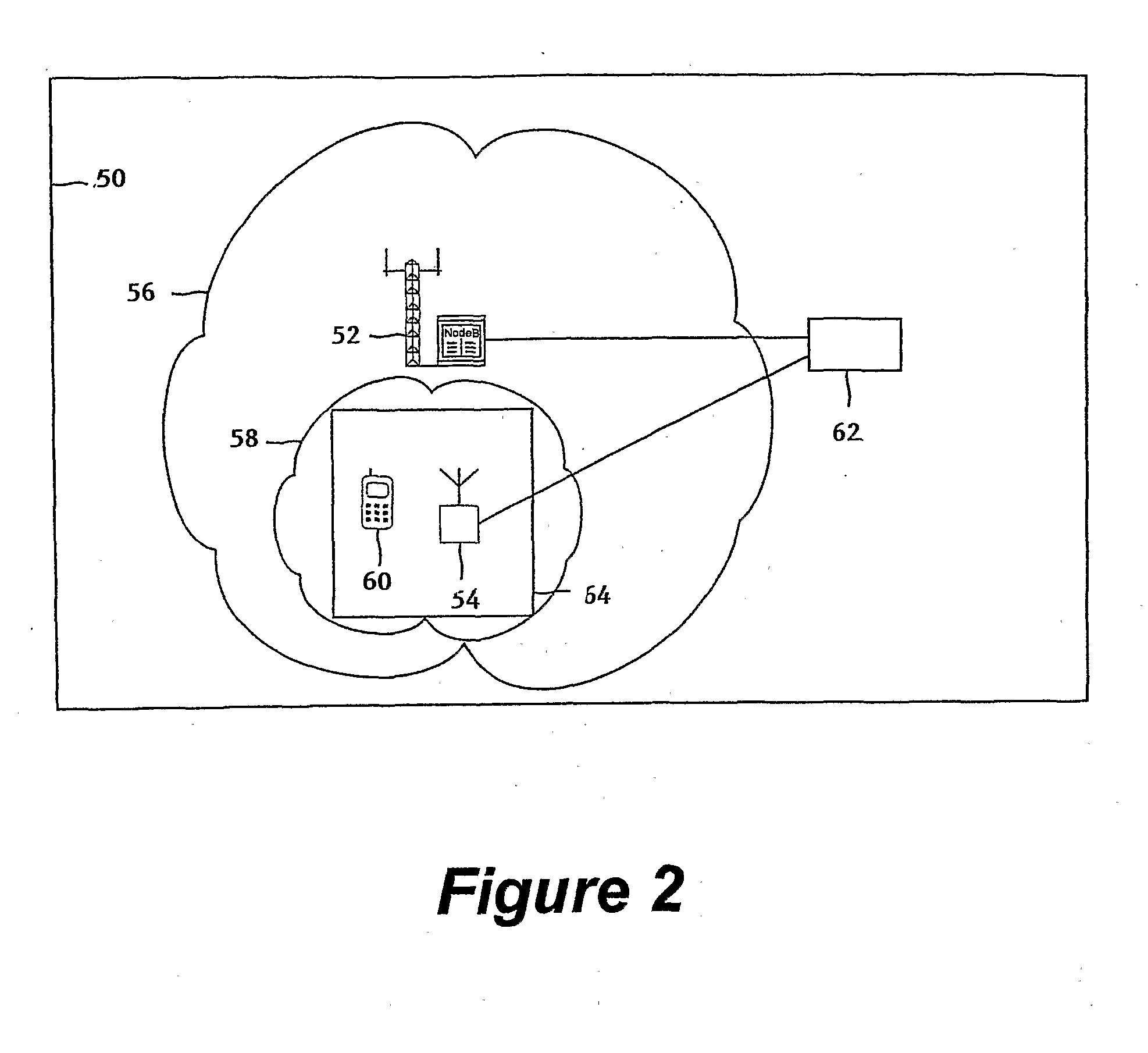
[0033] The operation of a preferred embodiment of the invention will now be described in more detail. FIG. 2, illustrates the typical deployment of a Public Land Mobile Network (PLMN) 50, including a Node B 52 and a LNN 54. Although only a single Node B is illustrated, multiple additional Node B's will be present in the PLMN and controlled by one or more RNCs (not shown).

[0034] The Node B has a cell coverage represented by area 56, while the LNN has coverage represented by area 58.

[0035] The diagram shows the overlapping coverage between the macro-cell 56 of the Node B and the pico-cell 58 of the LNN. The User Equipment 60 is located primarily within the pico-cell for connection with the LNN. Both the Node B and the LNN are connected to the rest of the PLMN network 62.

[0036] The term user equipment will be understood to include any device with 3G capabilities, including mobile terminals such as mobile phones, and personal digital assistants, laptops, or other palm-held or hand-he...


PUM


Abstract

The invention relates to a method and system of setting transmitter power levels, particularly in a Local Network Node transmitter, providing a pico cell for private use. A User Equipment (UE) is used to make measurements of the transmission link properties, such as downlink power and round trip time. Based on the measurements made at one or a plurality of locations, the power of the Local Network Node can be determined such that interference is minimised with any overlying cells of a macro-network. Call handovers between the UE and the cell of a macro network can also be arranged based on properties measure by the UE

Description

[0001] The invention relates to a communication system and in particular a method and system for adjusting the transmitter power levels within that communication system. [0002] This invention relates to a 3G cellular communication system and in particular the Frequency Division Duplex or Time Division Duplex (FDD / TDD) mode of the Wideband Code Division Multiple Access (WCDMA) system defined by the Third Generation measurement processor Partnership Project (3GPP). This is described in more detail at www.3gpp.org. [0003] The 3G cellular communication system provides subscribers with the ability to transmit text, digitised voice, video and other multi-media data from their mobile handset. The system is presently implemented by the Universal Mobile Telecommunications System (UMTS) which builds on the existing Global System for Mobile Communications (GSM) network and General Packet Radio Service (GPRS) technology. The initial specification for UMTS were referred to as ‘Release 99’, (R99)...

Claims


Application Information

Patent Timeline
Patent Type & Authority Applications(United States)
IPC IPC(8): H04Q7/00H04W4/02H04W36/12H04W52/00H04W52/24H04W52/28H04W52/34H04W52/36
CPCH04W36/12H04W52/247H04W52/283H04W52/34H04W52/36H04W48/18H04W52/244H04B17/26H04B17/327H04W4/008H04W4/023H04W84/105
Inventor RICHARDSON, ANDREW
Owner COMMSCOPE TECH LLC
Why Eureka
Try Eureka