Method And System For Controlling And Monitoring An Array Of Point-Of-Load Regulators

a point-of-load regulator and array technology, applied in the direction of electric variable regulation, process and machine control, instruments, etc., can solve the problems of large circuit board area, inability to deliver relatively high current at low voltage over a relatively long distance, and congestion of signal line routing

Inactive Publication Date: 2008-03-20
BEL POWER SOLUTIONS INC
View PDF99 Cites 24 Cited by
  • Summary
  • Abstract
  • Description
  • Claims
  • Application Information

AI Technical Summary

Benefits of technology

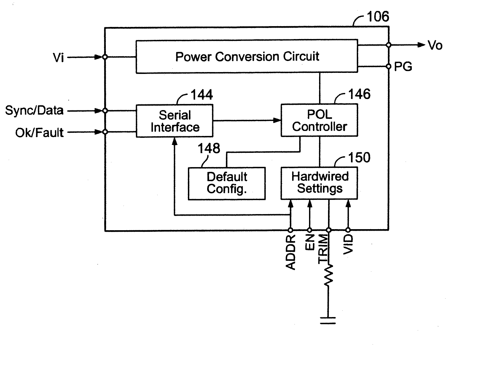
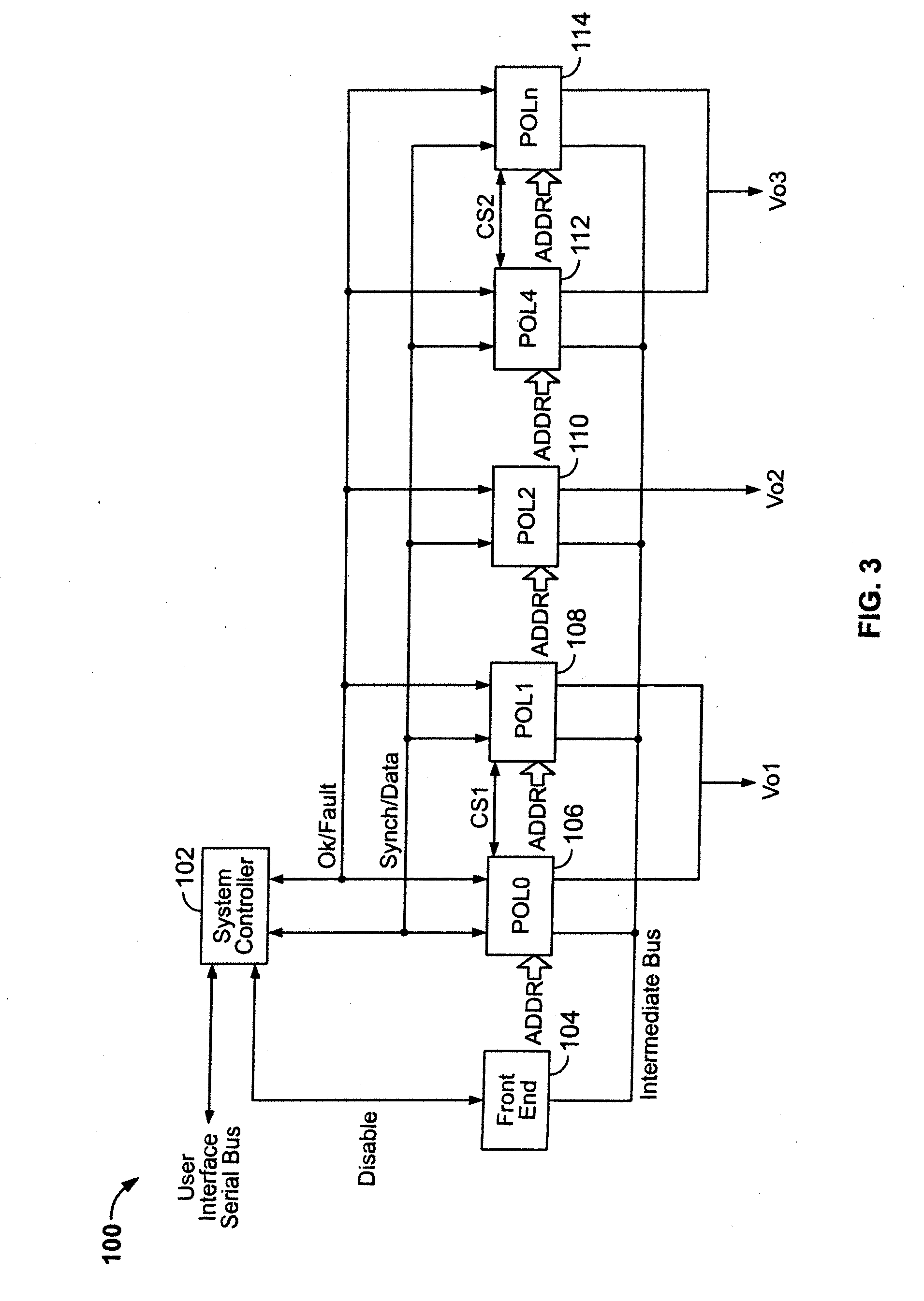
[0067] It should be appreciated that the POL control system of the present invention provides certain advantages over prior art distributed power distribution systems. The present POL control system requires much less complexity or “glue” components (e.g., mediating devices) in order to provide communication and control of a plurality of POL regulators, thereby reducing the amount of circuit board space for the POL control system and number of control lines needed for communication, control and monitoring. The POL control system is easily scalable by adding POL regulators to the array in order to support additional power requirements, without increasing the overhead requirements.

Problems solved by technology

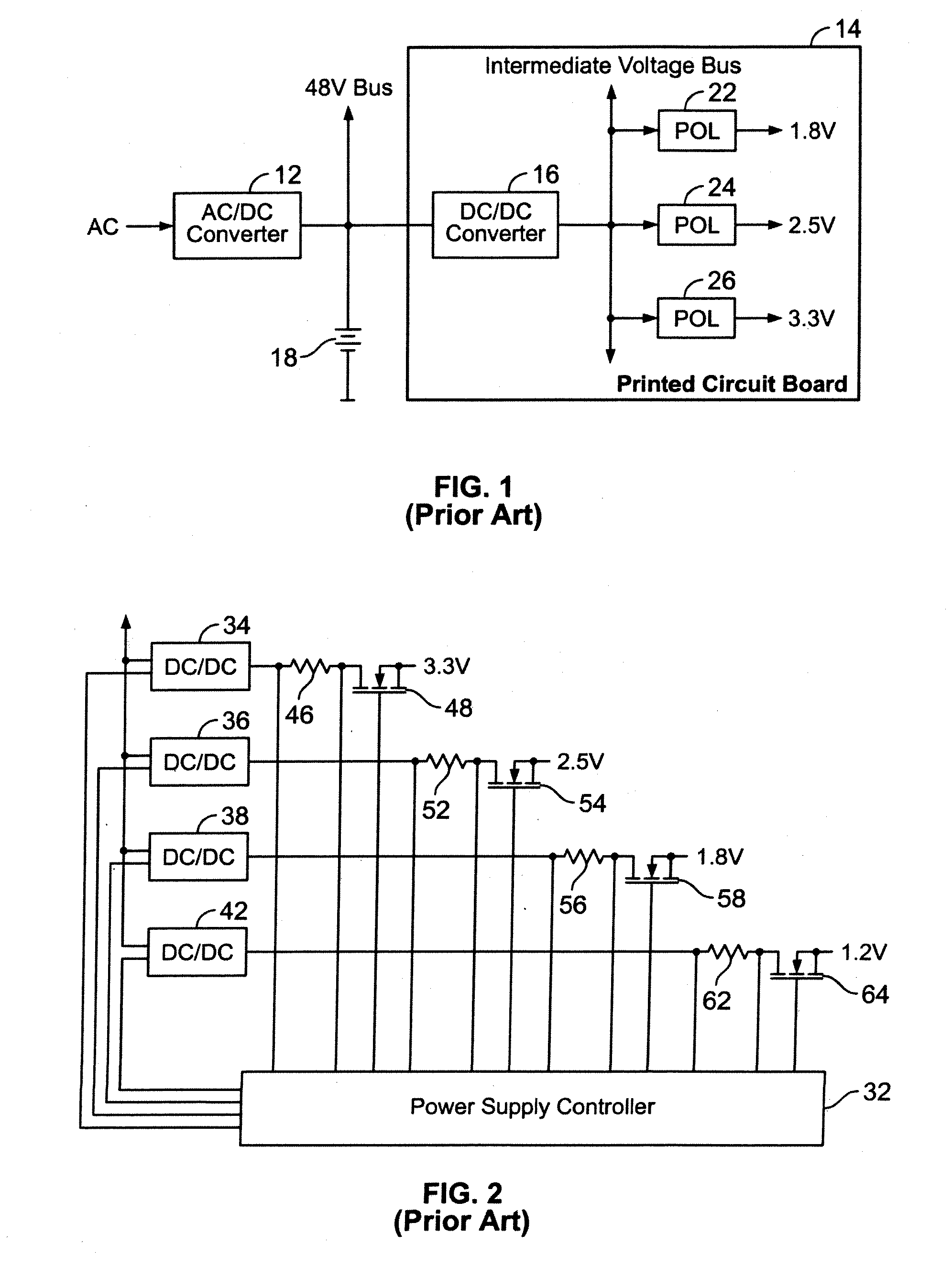
With the increasing complexity of electronic systems, it is common for an electronic system to require power provided at several different discrete voltage and current levels.
It is undesirable to deliver relatively high current at low voltages over a relatively long distance through an electronic device for a number of reasons.
First, the relatively long physical run of low voltage, high current lines consumes significant circuit board area and congests the routing of signal lines on the circuit board.
Second, the impedance of the lines carrying the high current tends to dissipate a lot of power and complicate load regulation.
Third, it is difficult to tailor the voltage / current characteristics to accommodate changes in load requirements.
A drawback with such a control system is that it adds complexity and size to the overall electronic system.

Method used


Image

  • Method And System For Controlling And Monitoring An Array Of Point-Of-Load Regulators
  • Method And System For Controlling And Monitoring An Array Of Point-Of-Load Regulators
  • Method And System For Controlling And Monitoring An Array Of Point-Of-Load Regulators

Examples


first embodiment

[0060] The system controllers from each the POL control systems would communicate with a host controller 240 via the user interface serial bus. As described above, the link with the host controller 240 enables the communication of monitoring, control and programming data. The host controller 240 may additionally be coupled to a local area network (LAN) or wide area network (WAN). A user would then have several options for accessing the POL control systems for purposes of monitoring, controlling and / or programming the POL control systems. In a first embodiment, a user system 266 (i.e., computer) equipped with a suitable application programming interface (API) may be coupled directly to the user interface bus for receiving communicating with the system controllers of the Systems A and B. The user system would likely include a user interface, such as a graphical user interface (GUI), that enables the display of status information regarding the POL control systems. The GUI may also serv...

second embodiment

[0061] Alternatively, in a second embodiment, the user system 264 may instead be coupled directly to the host controller 240. This might enable the same level of access to the POL control systems, or the host controller 240 may limit the extent of access (e.g., monitoring only, without ability to control or program). In yet another alternative, the user system 262 may be coupled to the host controller 240 through a LAN / WAN, thereby enabling the user to access the POL control systems from a remote location. As in the preceding embodiment, the host controller 240 may limit the extent of access to the POL control systems.

[0062]FIG. 10 illustrates another exemplary embodiment of a POL control system implemented with a host system. The POL control system includes two separate POL control systems similar to that described above with respect to FIG. 3. Unlike the embodiment of FIG. 9, the two POL control system 320, 310 each include a plurality of POL regulators without separate system con...


PUM


Abstract

A power control system comprises a plurality of POL regulators, at least one serial data bus operatively connecting the plurality of POL regulators, and a system controller connected to the serial data bus and adapted to send and receive digital data to and from the plurality of POL regulators. The serial data bus further comprises a first data bus carrying programming and control information between the system controller and the plurality of POL regulators. The serial data bus may also include a second data bus carrying fault management information between the system controller and the plurality of POL regulators. The power control may also include a front-end regulator providing an intermediate voltage to the plurality of POL regulators on an intermediate voltage bus.

Description

RELATED APPLICATION DATA [0001] This application claims priority as a continuation-in-part pursuant to 35 U.S.C. § 120 to patent application Ser. No. 10 / 326,222, filed Dec. 21, 2002, and patent application Ser. No. 10 / 293,001, filed Nov. 13, 2002.BACKGROUND OF THE INVENTION [0002] 1. Field of the Invention [0003] The present invention relates to power control systems, or more particularly, to a method and system to control and monitor an array of point-of-load regulators. [0004] 2. Description of Related Art [0005] With the increasing complexity of electronic systems, it is common for an electronic system to require power provided at several different discrete voltage and current levels. For example, electronic systems may include discrete circuits that require voltages such as 3v, 5v, 9v, etc. Further, many of these circuits require a relatively low voltage (e.g., 1v), but with relatively high current (e.g., 100A). It is undesirable to deliver relatively high current at low voltage...

Claims


Application Information

Patent Timeline
Patent Type & Authority Applications(United States)
IPC IPC(8): G06F1/26
CPCG06F1/26H02J2001/008H02J1/08H02J1/082G06F1/28
Inventor CHAPUIS, ALAINGUZ, MIKHAILROARK, DENNIS R.
Owner BEL POWER SOLUTIONS INC
Why Eureka
Try Eureka