
Floodable Optical Apparatus, Methods and Systems

Active Publication Date: 2016-04-07
GEOSPACE TECH
View PDF5 Cites 10 Cited by
  • Summary
  • Abstract
  • Description
  • Claims
  • Application Information

AI Technical Summary

Benefits of technology

The patent text describes a design and construction method for a seismic surveying and monitoring apparatus that allows for less complexity, material costs, and maintenance costs. The apparatus includes floodable optical cables and fiber conduits that can be entered by seawater during deployment, creating a pressure-balance. A floodable sensor station can also be provided for permanent reservoir monitoring with a long-term lifespan. The various embodiments of the invention utilizing floodable optical cables, conduits, and sensor stations can result in significant savings in manufacturing, deployment, and maintenance costs.

Problems solved by technology

Over long distances the optical signal may be overwhelmed by the tint, resulting in excessive optical signal attenuation.

Method used


Image

  • Floodable Optical Apparatus, Methods and Systems
  • Floodable Optical Apparatus, Methods and Systems
  • Floodable Optical Apparatus, Methods and Systems

Examples


Embodiment Construction

[0016]This disclosure is related generally to the field of marine seismic surveying and / or monitoring. For example, this disclosure may have applications in marine seismic surveying and / or monitoring, in which one or more seismic sources may be used to generate wavefields that interact with subsurface formations, and seismic sensors—either towed or ocean bottom—receive seismic energy generated by the seismic sources, or naturally occurring seismic events, and affected by the interaction with the subsurface formation. “Seafloor” and “ocean bottom”, as used herein, refer to a floor of a body of water, such as an ocean, a sea, or a lake, for example, whereas “subsea” refers to being under the surface of the body of water, possibly at or near the floor. The body of water can be a salt-water body of water, a fresh-water body of water, or a brackish body of water.

[0017]The standard design approach to protect optical fibers from hydrogen darkening and marine-related degradation mechanisms ...


PUM


Abstract

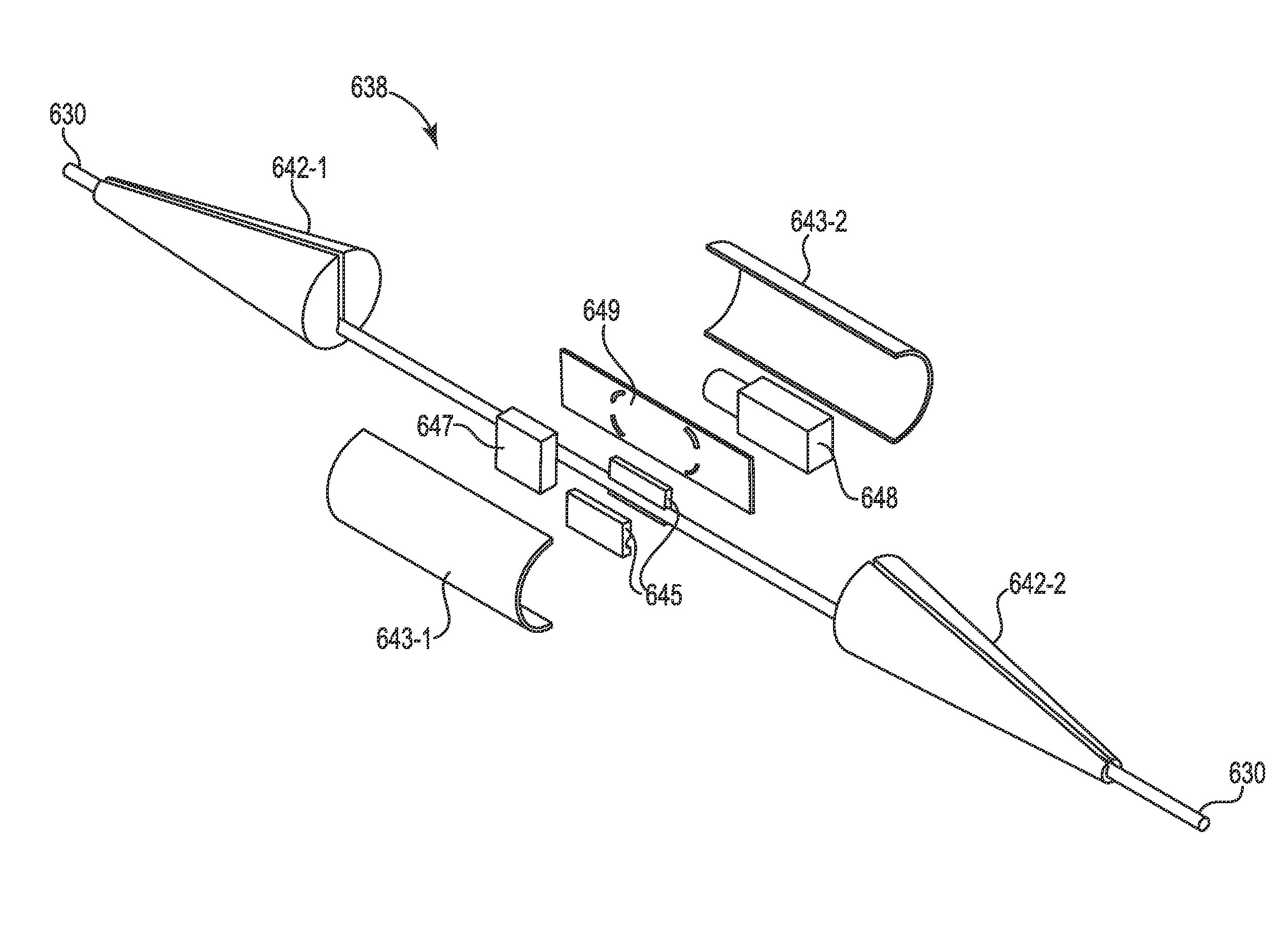
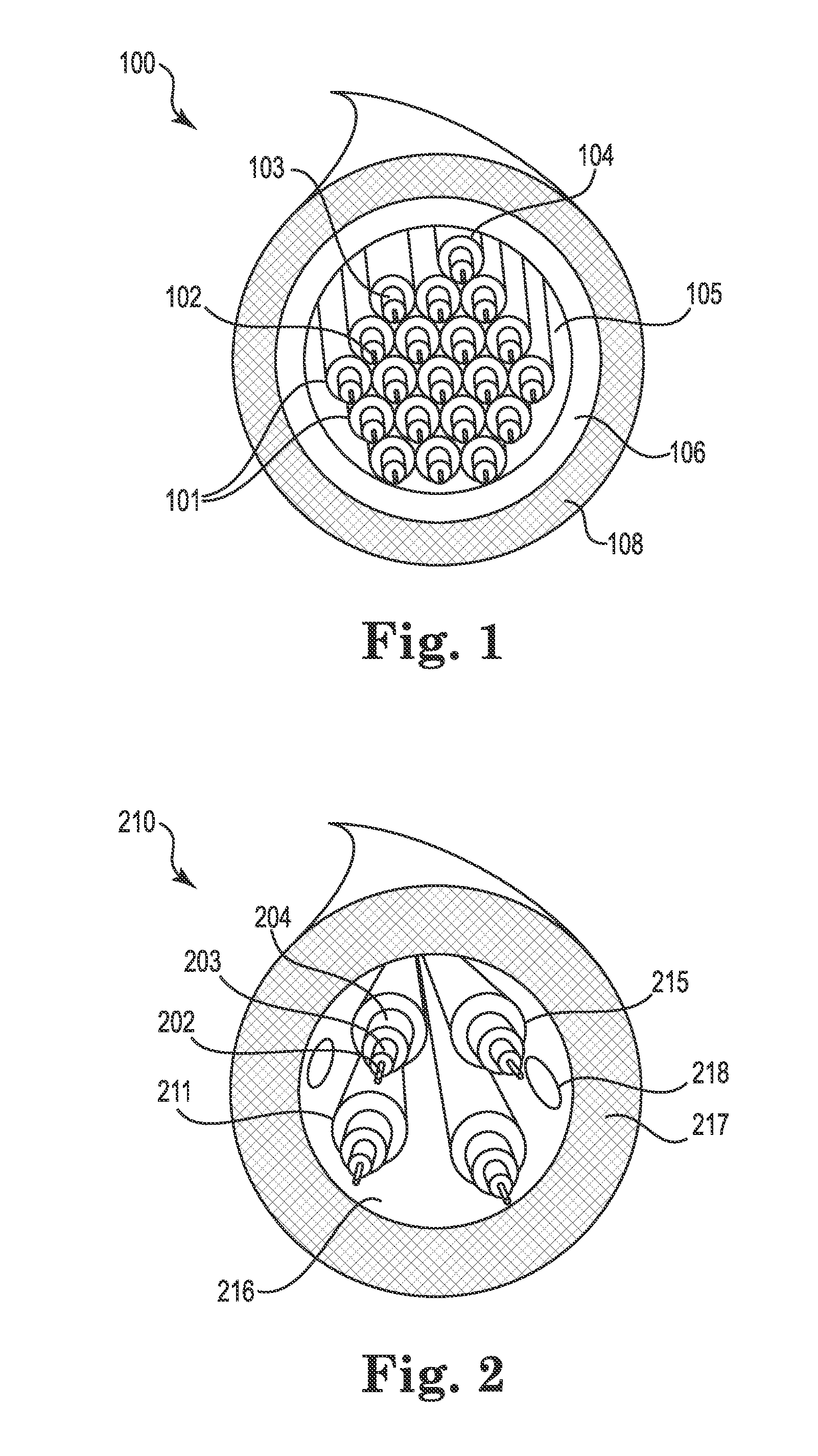
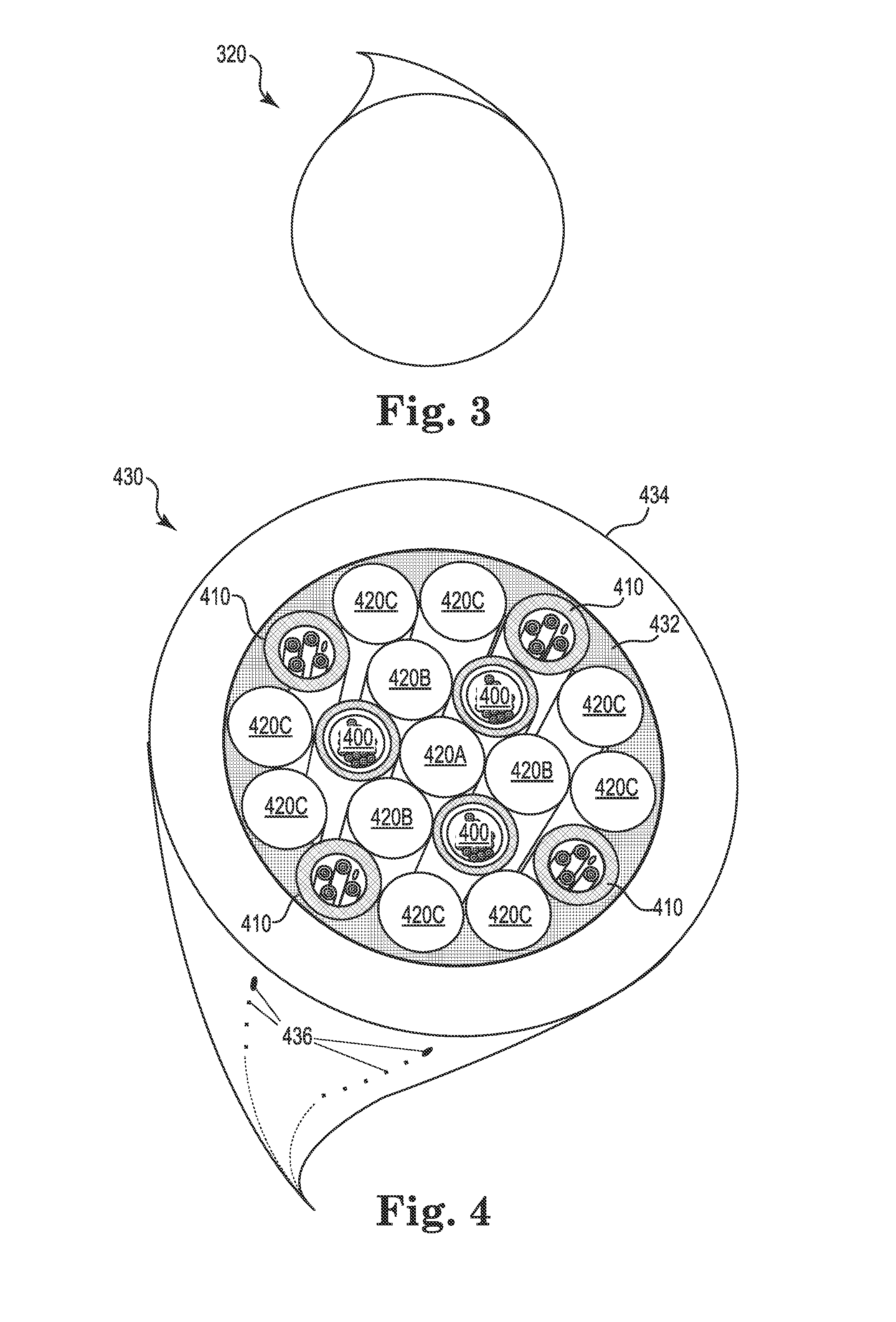
According to one example, a floodable sensor station is coupled to an optical cable. The optical cable may be floodable. The floodable sensor station may connect floodable optical cables as part of a permanent reservoir monitoring system. The floodable optical cable may house a plurality of floodable optical fiber conduits. The floodable sensor station may be pressure-balanced with its surrounding environment in high-pressure marine depths of 1500 meters or more.

Description

CROSS-REFERENCE TO RELATED APPLICATIONS[0001]This application claims priority to U.S. Provisional Application No. 62 / 059,271, filed Oct. 3, 2014, which is incorporated by reference.BACKGROUND[0002]Optical fibers are commonly employed for communicating data at high bandwidths. The investments to develop fiber optic communications technology have focused on making such bandwidths available over long distances. The long distances further necessitate producing cables that are simultaneously affordable and robust.[0003]Fiber Optic cables typically must resist not only the traumas associated with transport and installation, but also the insidious effects of aging and long-term exposure to the elements, including environmental contaminants. One such example in a marine environment is referred to as the hydrogen darkening effect. Over a long exposure time, hydrogen, whether arising from corrosion, biological processes, or other marine-related causes, may diffuse into a core of an optical fi...

Claims


Application Information

Patent Timeline
IPC IPC(8): G01V1/38G01V1/22G01P15/18
CPCG01V1/3808G01V1/226G01P15/18H01L29/16G02B6/443G01V1/18G02B6/4423G02B6/4427G01V1/188G01V2210/1427H04B10/25891
Inventor FERNIHOUGH, ROBERT ALEXIS PEREGRINSMITH, JEREMY CRANE
Owner GEOSPACE TECH
Learn More