System and Method for Controlling Operations of Air-Conditioning System

a technology of air-conditioning system and control system, which is applied in the direction of lighting and heating apparatus, heating types, instruments, etc., can solve the problems of inability to accurately describe the cost function representing the tracking error is reduced, and the model that accurately describes the operation of vapor compression system at one point in time may not be accurate at a later time. , to achieve the effect of reducing the cost function, reducing the error, and reducing the error

Active Publication Date: 2016-09-08
MITSUBISHI ELECTRIC RES LAB INC
View PDF11 Cites 10 Cited by
  • Summary
  • Abstract
  • Description
  • Claims
  • Application Information

AI Technical Summary

Benefits of technology

[0012]The solution to the virtual control problem is the control inputs, i.e., the coefficients of the simpler model, reducing a cost function representing the tracking error. This realization allows using control theory methods to virtually control the virtual control problem to determine the coefficients of the simpler model.
[0013]Accordingly, one embodiment of the invention discloses a method for controlling an operation of an air-conditioning system generating airflow in a conditioned environment. The method includes determining values of the airflow measured in the conditioned environment during the operation of the air-conditioning system; updating a model of airflow dynamics connecting values of flow and temperature of air conditioned during the operation of the air-conditioning system, wherein the updating iteratively reduces an error between values of the airflow determined according to the model and the measured values of the airflow; modeling the airflow using the updated model; and controlling the operation of the air-conditioning system using the modeled airflow. The steps of the method are performed using at least one processor of a controller.
[0014]Another embodiment discloses a system for controlling an operation of an air-conditioning system generating airflow in a conditioned environment including a set of sensors for measuring values of the airflow in the conditioned environment; and a controller for controlling the operation based on the airflow. The controller includes a memory storing a model of airflow dynamics connecting values of flow and temperature of air conditioned during the operation of the air-conditioning system, and a processor for updating iteratively the model of airflow dynamics to reduce an error between values of the airflow determined according to the model and the values of the airflow measured during the operation.
[0015]Yet another embodiment discloses an air-conditioning system including a user input interface for receiving a setpoint; an evaporator having a fan for adjusting an air-flow rate through a heat exchanger; a condenser having a fan for adjusting the air-flow rate through the heat exchanger; a compressor having a speed for compressing and pumping refrigerant through the system; an expansion valve for providing an adjustable pressure drop between a high-pressure portion and a low-pressure portion of the vapor compression system; a set of sensors for measuring values of the airflow in the conditioned environment; and a controller for controlling the operation based on the airflow to achieve the setpoint. The controller includes a memory storing a model of airflow dynamics connecting values of flow and temperature of air conditioned during the operation of the air-conditioning system, and a processor for updating iteratively the model of airflow dynamics to reduce an error between values of the airflow determined according to the model and the values of the airflow measured during the operation.

Problems solved by technology

The command inputs to the vapor compression system that delivers that particular amount of heat are often not unique and the various combinations of components consume different amounts of energy.
However, the air-conditioning systems are known to vary over time.
A model that accurately describes the operation of a vapor compression system at one point in time may not be accurate at a later time as the system changes, for example, due to slowly leaking refrigerant or the accumulation of corrosion on the heat exchangers.
In addition, the models of the air-conditioning system often ignore installation-specific characteristics such as room size, causing the model of the air-conditioning system to deviate from operation of the system.
However, the physical model of the airflow is of infinite dimension and too complex to be used in real time control applications.

Method used


Image

  • System and Method for Controlling Operations of Air-Conditioning System
  • System and Method for Controlling Operations of Air-Conditioning System
  • System and Method for Controlling Operations of Air-Conditioning System

Examples


Embodiment Construction

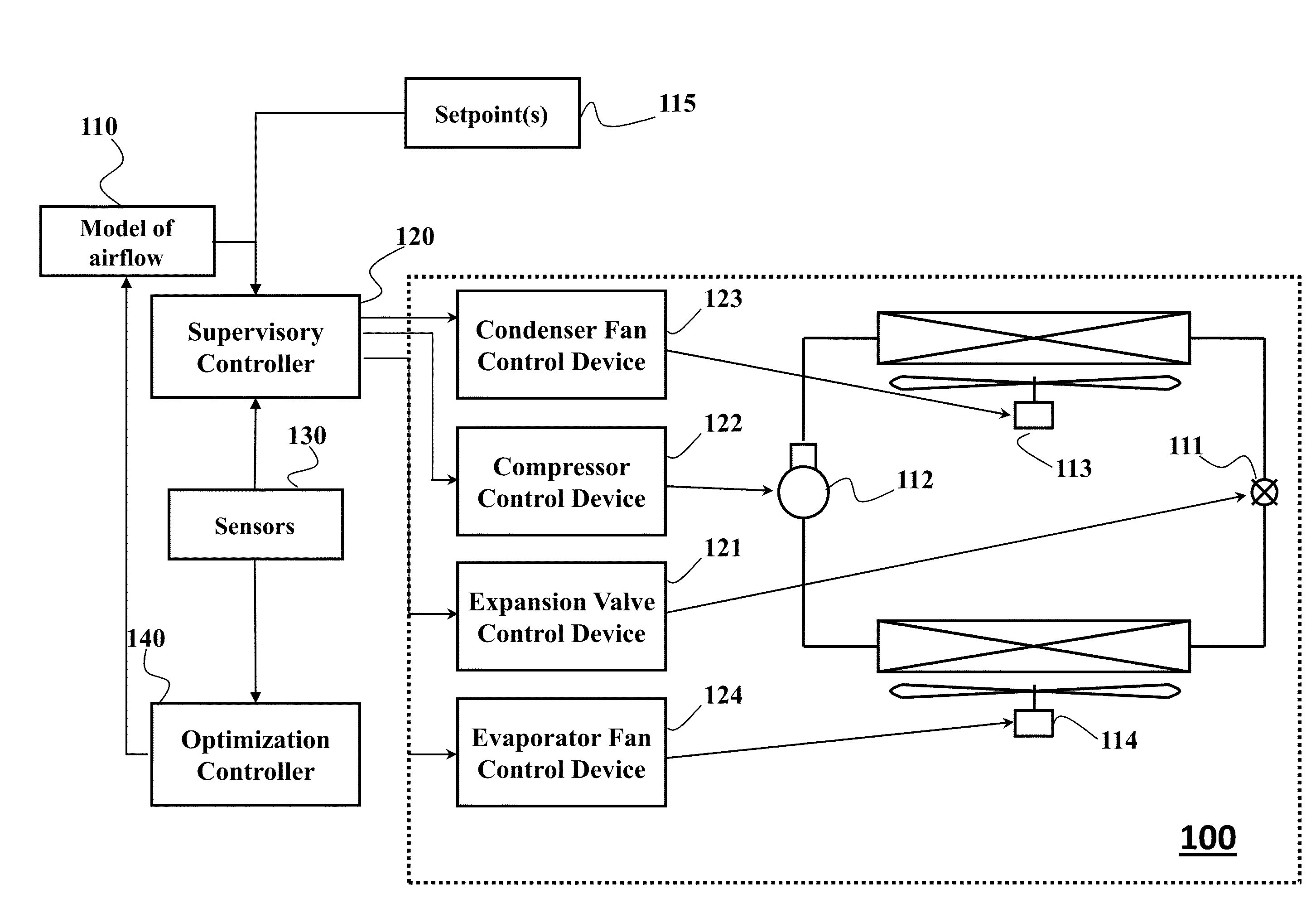
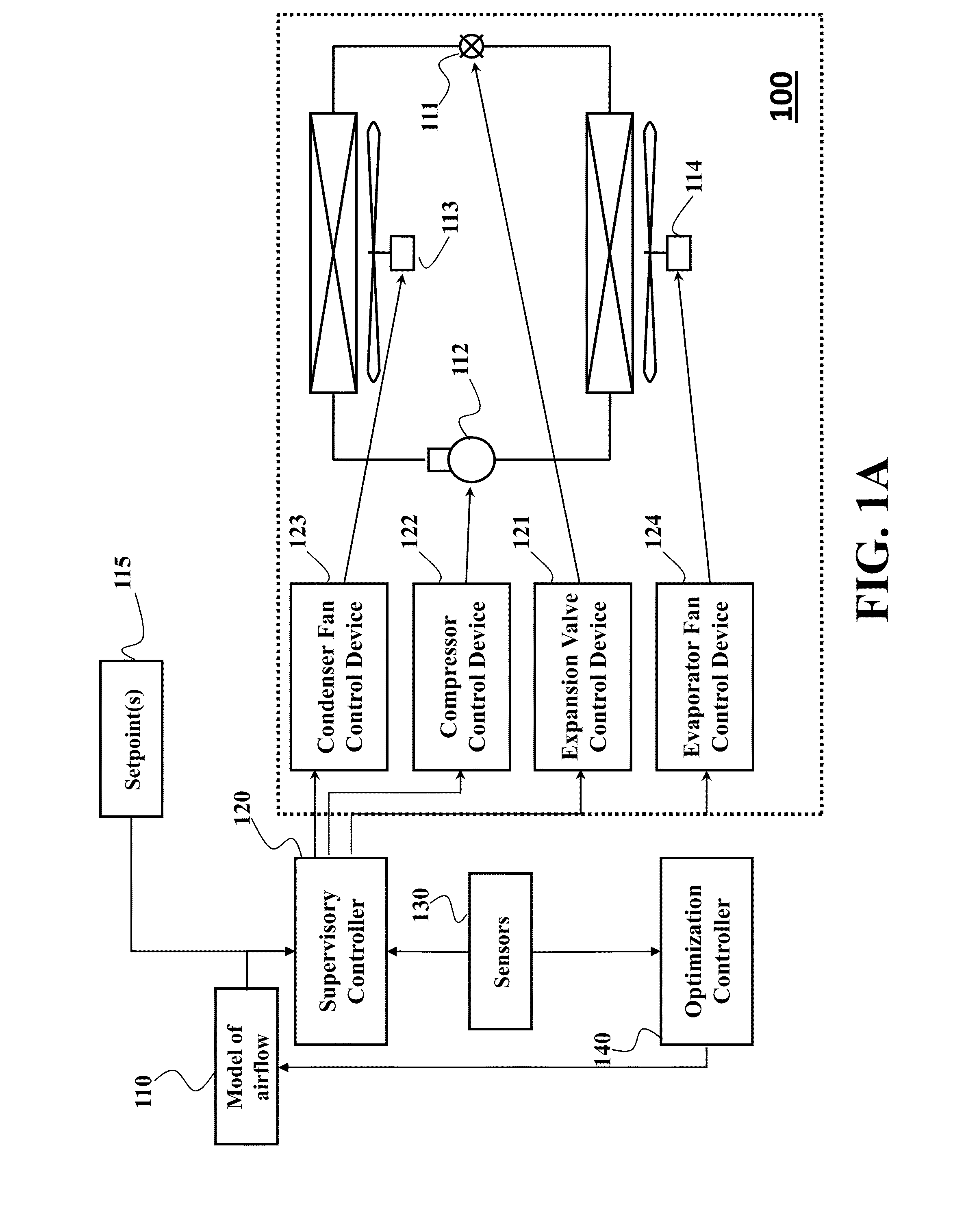
[0036]FIG. 1A shows a block diagram of an air-conditioning system 100 according to one embodiment of the invention. The system 100 can include one or a combination of components such an evaporator fan 114, a condenser fan 113, an expansion valve 111, and a compressor 112. The system can be controlled by a controller 120 responsible for accepting set-points 115, e.g., from a thermostat, and readings of a sensor 130, and outputting a set of control signals for controlling operation of the components. A supervisory controller 120 is operatively connected to a set of control devices for transforming the set of control signals into a set of specific control inputs for corresponding components. For example, the supervisory controller is connected to a compressor control device 122, to an expansion valve control device 121, to an evaporator fan control device 124, and to a condenser fan control device 123.

[0037]The supervisory controller is operatively connected to a model of the airflow d...


PUM


Abstract

A method controls an operation of an air-conditioning system generating airflow in a conditioned environment. The method updates a model of airflow dynamics connecting values of flow and temperature of air conditioned during the operation of the air-conditioning system. The model is updated interactively iteratively to reduce an error between values of the airflow determined according to the model and values of the airflow measured during the operation. Next, the method models the airflow using the updated model and controls the operation of the air-conditioning system using the model.

Description

FIELD OF THE INVENTION[0001]This invention relates generally to air-conditioning systems, and more particularly to controlling operations of the air-conditioning system.BACKGROUND OF THE INVENTION[0002]Air-conditioning systems, such as heating, ventilating and air conditioning (HVAC) system, are widely used in industrial and residential applications. For example, the air-conditioning system can include one or a combination of variable speed compressors, variable position valves, and variable speed fans to the vapor compression cycle to deliver particular amount of heat. The command inputs to the vapor compression system that delivers that particular amount of heat are often not unique and the various combinations of components consume different amounts of energy. Therefore, it is desirable to operate the vapor compression system using the combination of inputs that minimizes energy and thereby maximizes efficiency.[0003]Conventionally, methods maximizing the energy efficiency rely o...

Claims


Application Information

Patent Timeline
Patent Type & Authority Applications(United States)
IPC IPC(8): F24F11/00G05B17/02
CPCF24F11/006F24F11/001F24F11/0076F24F2011/0075F24F2011/0047F24F2011/0063F24F2011/0064G05B17/02G05B13/04G05D23/1917F24F11/64F24F11/84F24F11/86F24F11/46F24F11/79F24F11/30F24F2110/00F24F2140/60F24F11/65F24F11/70F24F11/62
Inventor BENOSMAN, MOUHACINEBOUFOUNOS, PETROSKRAMER, BORISGROVER, PIYUSH
Owner MITSUBISHI ELECTRIC RES LAB INC
Why Eureka
Try Eureka