
Planning system for an autonomous work vehicle system

a technology for autonomous work and planning system, applied in vehicle position/course/altitude control, process and machine control, instruments, etc., can solve problems such as product management, inefficient management, product management, etc., and achieve the effect of reducing a cost function and a cost function

Active Publication Date: 2018-12-20
AUTONOMOUS SOLUTIONS +1
View PDF1 Cites 10 Cited by
  • Summary
  • Abstract
  • Description
  • Claims
  • Application Information

AI Technical Summary

Benefits of technology

The patent describes a planning system for autonomous work vehicles that can create a route through a field based on multiple costs associated with operation of the vehicles. These costs include obstacle management, positioning, product management, and more. The system can also determine an optimal time to initiate the plan and how to execute it. The technical effect of this system is to improve the efficiency and effectiveness of autonomous work vehicles in terms of cost savings and operational improvements.

Problems solved by technology

In addition, the costs include an obstacle management cost associated with traversing an obstacle, a positioning cost associated with positioning a processing assembly in a processed region of the field, a direction cost associated with traversing the field in a less suitable direction, a product management cost associated with inefficient management of product storage, an outlet positioning cost associated with positioning a product outlet over an unprocessed region of the field, a compaction cost associated with not traversing a compaction lane, a partition order cost associated with not following a determined partition order, an entry point cost associated with not engaging the processing assembly at a field entry point, an exit point cost associated with not disengaging the processing assembly at a field exit point, an initiation time cost associated with not initiating the plan at a target time, or a combination thereof.
In addition, the costs include an obstacle management cost associated with traversing an obstacle, a positioning cost associated with positioning a processing assembly in a processed region of the field, a direction cost associated with traversing the field in a less suitable direction, a product management cost associated with inefficient management of product storage, an outlet positioning cost associated with positioning a product outlet over an unprocessed region of the field, a compaction cost associated with not traversing a compaction lane, a partition order cost associated with not following a determined partition order, an entry point cost associated with not engaging the processing assembly at a field entry point, an exit point cost associated with not disengaging the processing assembly at a field exit point, an initiation time cost associated with not initiating the plan at a target time, a passing cost associated with at least two autonomous work vehicle systems passing one another along adjacent swaths, an operation order cost associated with performing operations out of order, or a combination thereof.
In addition, the costs include an obstacle management cost associated with traversing an obstacle, a positioning cost associated with positioning a processing assembly in a processed region of the field, a direction cost associated with traversing the field in a less suitable direction, a product management cost associated with inefficient management of product storage, an outlet positioning cost associated with positioning a product outlet over an unprocessed region of the field, a compaction cost associated with not traversing a compaction lane, a partition order cost associated with not following a determined partition order, an entry point cost associated with not engaging the processing assembly at a field entry point, an exit point cost associated with not disengaging the processing assembly at a field exit point, an initiation time cost associated with not initiating the plan at a target time, or a combination thereof.

Method used


Image

  • Planning system for an autonomous work vehicle system
  • Planning system for an autonomous work vehicle system
  • Planning system for an autonomous work vehicle system

Examples


Embodiment Construction

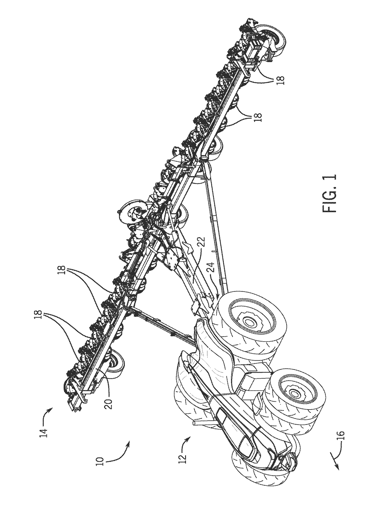
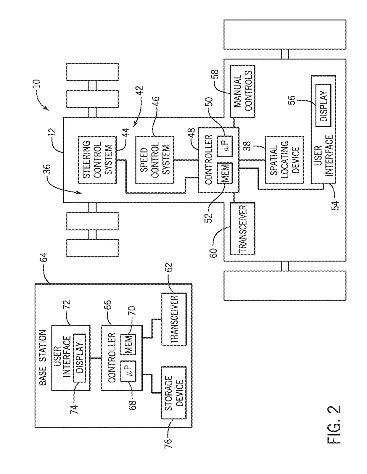
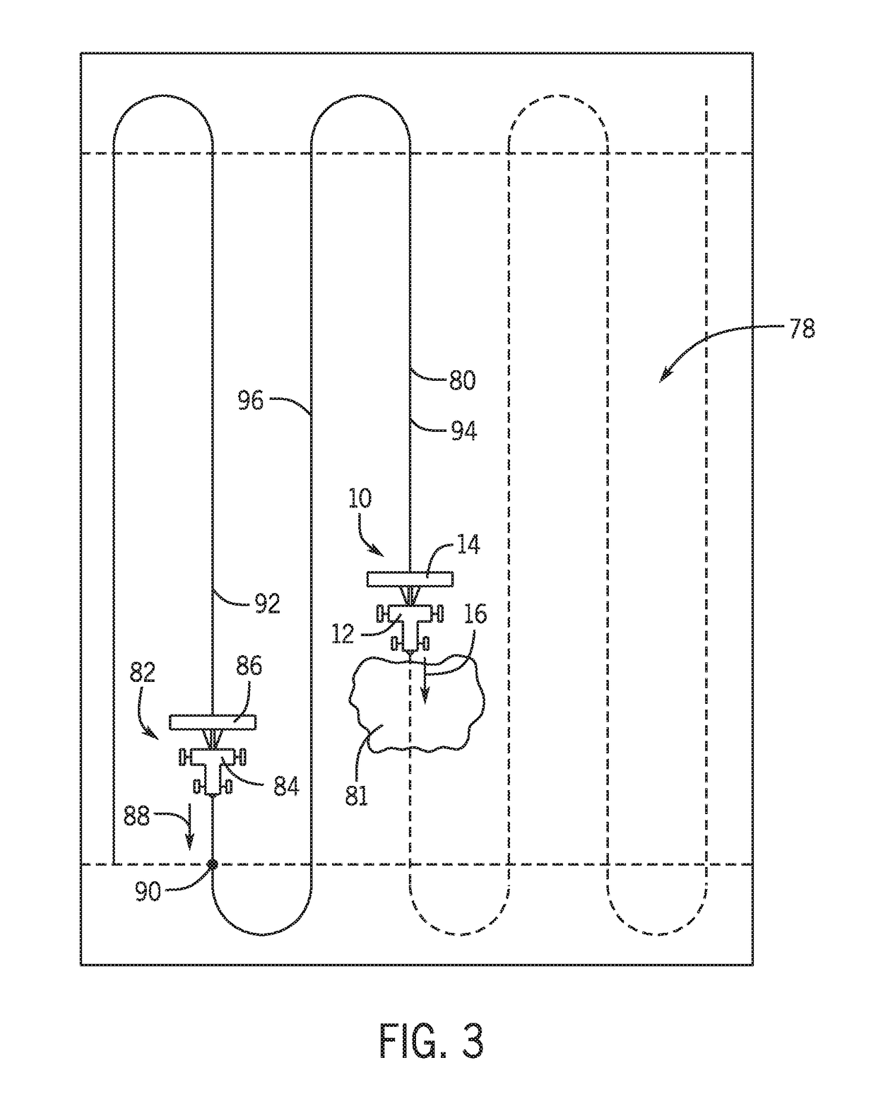
[0013]Turning now to the drawings, FIG. 1 is a perspective view of an embodiment of an autonomous work vehicle system 10 including an autonomous work vehicle 12 and an agricultural implement 14 coupled to the autonomous work vehicle 12. The autonomous work vehicle 12 includes a control system configured to automatically guide the autonomous work vehicle system 10 through a field (e.g., along a direction of travel 16) to facilitate agricultural operations (e.g., planting operations, seeding operations, application operations, tillage operations, harvesting operations, etc.). For example, the control system may automatically guide the autonomous work vehicle system 10 along multiple swaths through the field without input from an operator. The control system may also automatically guide the autonomous work vehicle system 10 around headland turns between swaths.

[0014]In the illustrated embodiment, the agricultural implement 14 is a planter having multiple row units 18 distributed along ...


PUM


Abstract

A planning system for an autonomous work vehicle system includes a controller configured to determine a plan for the autonomous work vehicle system by reducing a cost function, and to output one or more signals indicative of the plan and / or instructions to execute the plan. The plan includes a route of the autonomous work vehicle system through a field, and the cost function includes multiple costs associated with operation of the autonomous work vehicle system.

Description

BACKGROUND[0001]The disclosure relates generally to a planning system for an autonomous work vehicle system.[0002]Certain autonomous work vehicles are controlled based on a plan that is generated by the autonomous work vehicle and / or a base station, for example. The plan includes a list of tasks to be performed by the autonomous work vehicle. For example, if the autonomous work vehicle is performing agricultural operations (e.g., towing a seeder or planter, harvesting crops, etc.), the plan may include traversing multiple swaths through a field, thereby enabling the autonomous work vehicle to cover at least a portion of the field. The plan may be generated based on certain rules that control operation of the autonomous work vehicle. For example, the rules may include a rule to enter the field at a field entry point, a rule to exit the field at a field exit point, a rule to avoid obstacles, a rule to cover portions of the field in a certain order, a rule to follow certain paths to re...

Claims


Application Information

Patent Timeline
Patent Type & Authority Applications(United States)
IPC IPC(8): A01B69/04G05D1/02G06Q50/02G06Q10/06
CPCA01B69/008G05D1/0219G05D2201/0201G06Q50/02G06Q10/06313G05D1/0223G05D1/0217
Inventor FOSTER, CHRISTOPHER ALANPOSSELIUS, JOHN HENRYBUNDERSON, NATHAN ERICBYBEE, TAYLOR CHADMORWOOD, DANIEL JOHNTURPIN, BRET TODD
Owner AUTONOMOUS SOLUTIONS
Learn More