This helps you quickly interpret patents by identifying the three key elements:
Problems solved by technology
Method used
Benefits of technology
[0007] Briefly, the present invention comprises a knee pad construction which includes a first shell designed to fit over and protect the patella or knee of a workman. The first shell is coupled to a second member such as a strap or other construct, which is designed to engage or fit on the thigh of a workman and simultaneously be connected to or joined
Problems solved by technology
One problem associated with the use of knee pads relates to a situation where the pad will tend to slip or move while the workman or individual using the pad is changing
Method used
Image
Click on the blue label to locate the original text in one second.
Reading with bidirectional positioning of images and text.
Examples
Example
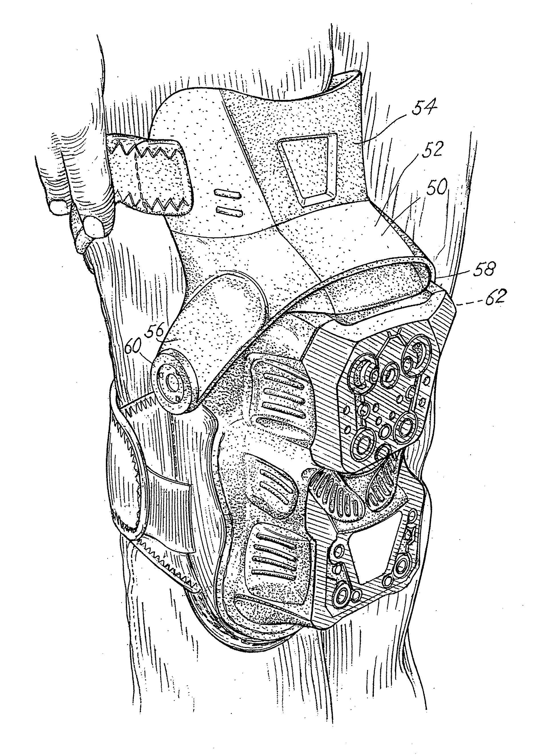
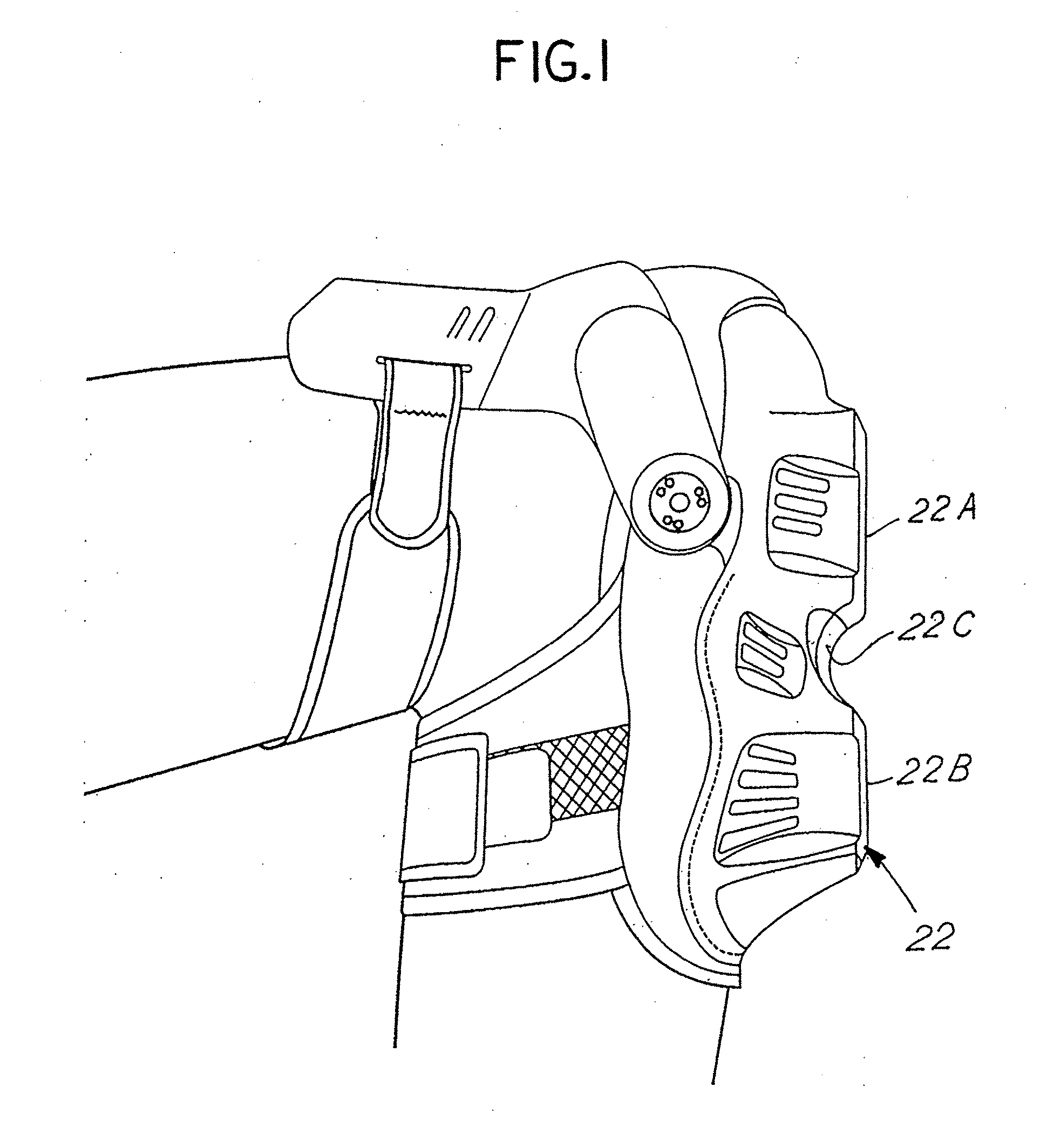
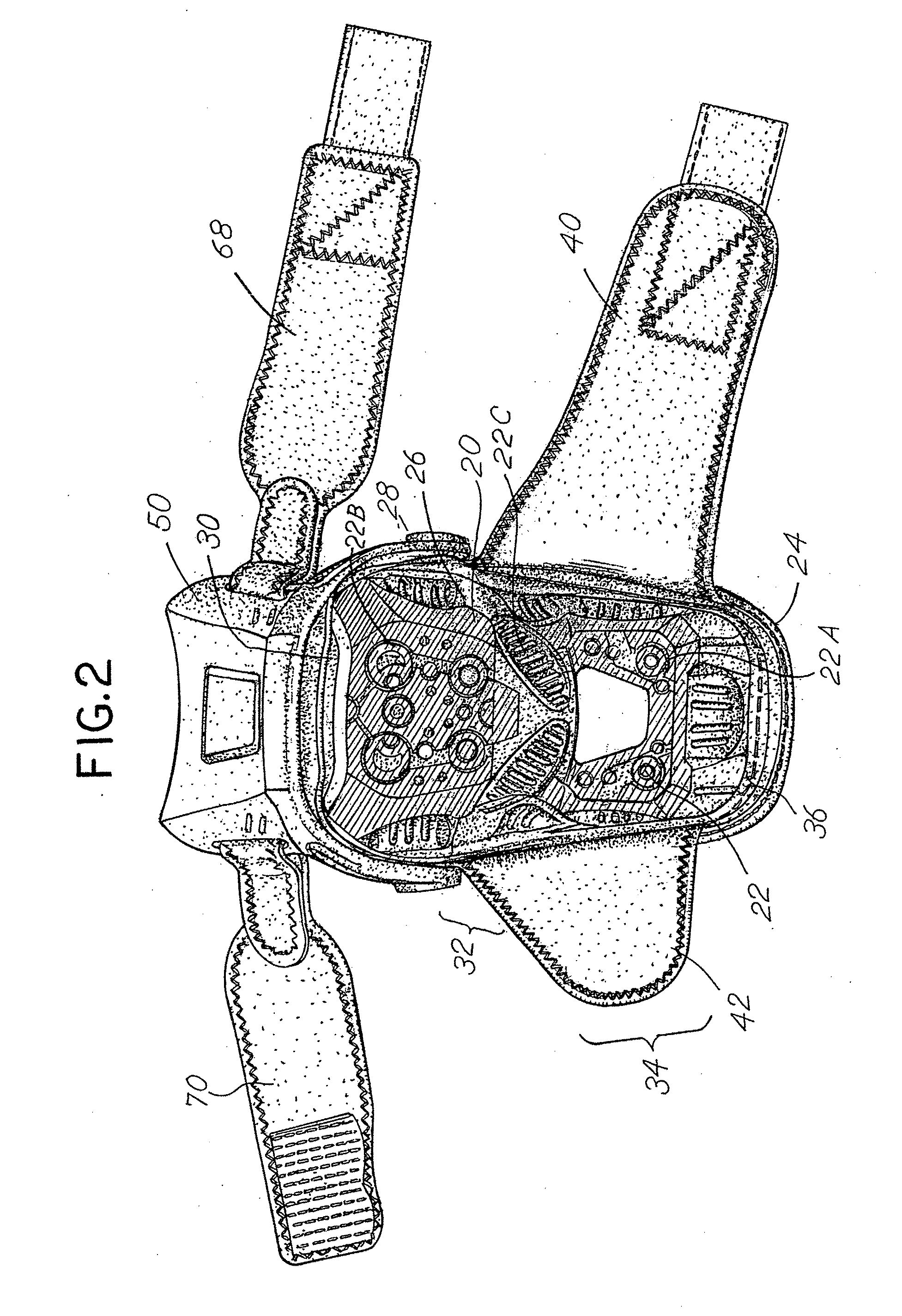
[0064]FIGS. 1-4 illustrate features associated with a first embodiment of the invention. The embodiment of FIGS. 1-4 comprises a protective knee pad which includes a first generally rigid, formed knee protection shell 20. The shell 20 includes an outer face 22. It further includes a peripheral edge 24, an inner concave section 26 with layer padding 27 with an optional gel insert 28. The hard shell 20 includes an upper section or end 30, a mid section 32 and a lower section or end 34. The upper side or end 30 is designed to fit over the top of a knee or patella. The mid-section 32 fits directly over the patella. The lower section 34 fits over the upper shin of an individual. The lower end or section 34 is generally cylindrical in shape and the extreme lower end extends outwardly and upwardly away from the shin in the manner of a duck bill 36.
[0065] The outer face 22 may have any number of desired forms. It may be generally convex. It may include a surface comprised of various flat s...
PUM
Abstract
Protective knee pads are comprised of a first shell member which fits over the patella and knee joint and a second member which is attached to the lower thigh and pivotally engaged with the knee pad shell so that they may articulate one with respect to the other while providing additional support and protection for the user of the knee pad. An additional shin pad may also be attached to the lower end of the shell which covers the knee.
Description
CROSS REFERENCE TO RELATED APPLICATIONS [0001] This is a continuation in part application of Ser. No. 11 / 679,021 filed Feb. 26, 2007 entitled “Knee Pad Constructions” which is a continuation in part application of Ser. No. 10 / 943,347, filed Sep. 17, 2004, entitled “Knee Pad Construction” which is a continuation in part application of Ser. No. 10 / 926,240, filed Aug. 25, 2004, entitled “Knee Pad Construction”, now U.S. Pat. No. 7,181,770 issued Feb. 27, 2007 and Ser. No. 11 / 670,297, filed Feb. 1, 2007, entitled “Knee Pad Construction”, each of which is incorporated herewith by reference and for which priority is claimed. BACKGROUND OF THE INVENTION [0002] In a principal aspect, the present invention relates to protective knee pad constructions and, more particularly, to pairs of knee pads for workmen which are constructed to cover and protect the lower thigh, knee and upper shin of a workman. [0003] Protective knee pads are used by various individuals; for example, construction worker...
Claims
Application Information
Patent Timeline
Application Date:The date an application was filed.
Publication Date:The date a patent or application was officially published.
First Publication Date:The earliest publication date of a patent with the same application number.
Issue Date:Publication date of the patent grant document.
PCT Entry Date:The Entry date of PCT National Phase.
Estimated Expiry Date:The statutory expiry date of a patent right according to the Patent Law, and it is the longest term of protection that the patent right can achieve without the termination of the patent right due to other reasons(Term extension factor has been taken into account ).
Invalid Date:Actual expiry date is based on effective date or publication date of legal transaction data of invalid patent.
IPC IPC(8): A41D13/06A41D13/00
CPCA41D13/065A41D13/0153A41D13/00
Inventor GODSHAW, DONALD E.REDZISZ, ANDREZJ M.HAI, DUSCHANTZ, BRAD L.