Electronic wind instrument and zero point compensation method therefor

a technology of electronic wind instruments and zero point compensation, which is applied in the direction of instruments, amplifier modifications to reduce noise influence, and selection arrangements, etc., can solve the problems of affecting the performance of the instrument, the zero point of the output signal of the breath flow detection section tends to easily move or shift, and the conversion efficiency of the player's breath flow into the final electrical signal is poor. , to achieve the effect of comfortable performan

Inactive Publication Date: 2008-03-27
YAMAHA CORP
View PDF12 Cites 5 Cited by
  • Summary
  • Abstract
  • Description
  • Claims
  • Application Information

AI Technical Summary

Benefits of technology

[0004]In view of the foregoing, it is an object of the present invention to provide an improved electronic wind instrument and zero point compensation method therefor which allow a human player to execute a comfortable performance even in a situation where the zero point of the output signal of a breath flow detector is liable to shift due to a temperature drift.

Problems solved by technology

Therefore, even when there has occurred a temperature drift in a zero point of an output signal of the pressure sensor, such a temperature drift has only a slight influence on the performance.
Because the breath flow detection section converts the human player's breath flow into a pressure in the open space and converts the pressure sensor into an electric signal by means of a pressure sensor, a conversion efficiency in converting the player's breath flow into the final electrical signal is very poor.
As a consequence, the zero point of the output signal of the breath flow detection section tends to easily move or shift due to a temperature drift.
If the zero point shifts to a minus (negative) side, note-on (tone generation start) of a tone tends be difficult, while, if the zero point moves to a plus (positive) side, a tone tends to keep sounding even after the end of a player's performance of the instrument.
Namely, the conventionally-known electronic wind instruments, such as an electronic flute, present the problem that a performance would be interfered with shifting, due to a temperature drift, of the zero point of the output signal of the breath flow detection section.

Method used


Image

  • Electronic wind instrument and zero point compensation method therefor
  • Electronic wind instrument and zero point compensation method therefor
  • Electronic wind instrument and zero point compensation method therefor

Examples


first embodiment

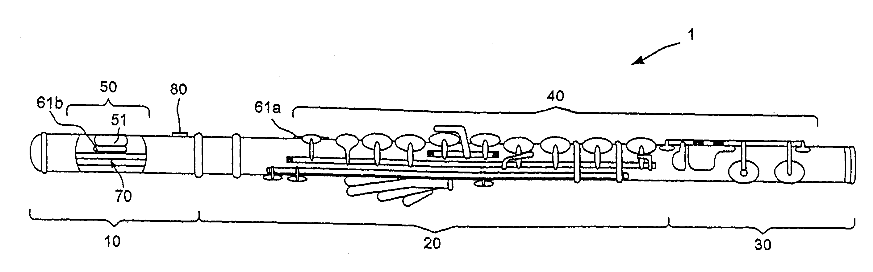
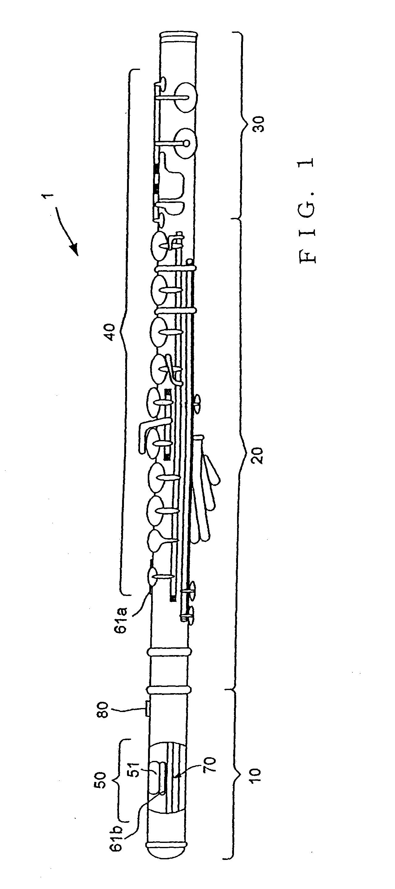
[0023]FIG. 1 is a view showing an outer appearance of an electronic flute that is constructed as a first embodiment of an electronic wind instrument of the present invention. As shown, the electronic flute of FIG. 1 includes a casing 1 that has a head pipe section 10, main pipe section 20 and tail pipe section 30. Performing keys 40, which are operators operable with fingers of a human player (user), are provided on the main pipe section 20 and tail pipe section 30, and a lip plate 50, which is an operator operable with lips of the human player, is provided on the head pipe section 10. Blow hole 51 is provided in the lip plate 50, and a breath flow detector 70 is provided on the lip plate 50. The breath flow detector 70 detects a flow (i.e., flow rate or amount) of breath air blown by the human player into the electronic flute through the blow hole 51 and thereby outputs breath flow data.

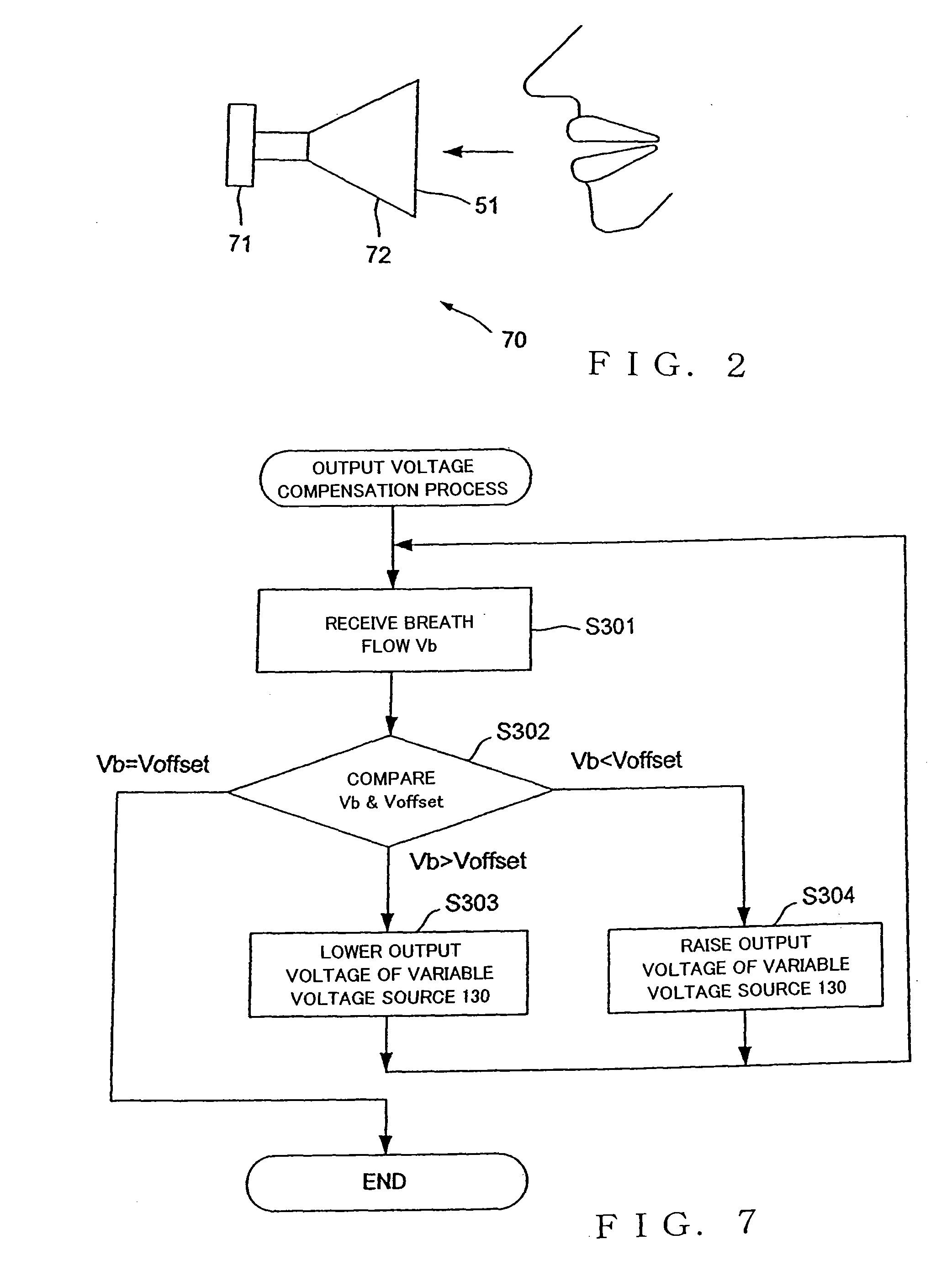
[0024]FIG. 2 is a view explanatory of how the breath flow detector 70 is constructed. The breath...

second embodiment

[0036]FIG. 5 is a block diagram showing a general electrical setup of an electronic flute according to a second embodiment of the present invention. Elements corresponding in construction and function to those in the first embodiment of FIG. 3 are indicated in FIG. 5 by the same reference numerals and will not be described to avoid unnecessary duplication.

[0037]The electronic flute according to the second embodiment includes a variable voltage source 130 as a power supply for supplying the adder 74 of the breath flow detector 70 with an offset-canceling voltage. Here, the adder 74 and variable voltage source 130 together constitute a shift control section (or device) for shifting output information, i.e. breath flow data Vb, of the breath flow detector 70 in the plus or minus direction. In the second embodiment, the CPU 100 performs zero point compensation processing 101A in place of the zero point compensation processing 101 employed in the first embodiment. The zero point compensa...


PUM


Abstract

Electronic wind instrument includes: a breath flow detector detecting a flow of breath blown by a user; a tone generator forming a tone signal; a control section controlling the tone generator on the basis of an output signal of the breath flow detector; and a zero point compensation section that, when a predetermined condition has been satisfied, compensates a zero point of the output signal of the detector on the basis of the output signal generated by the detector at the time point the predetermined condition has been satisfied. The predetermined condition is satisfied when it is detected that a zero point compensation switch operable by the user has been turned on, that no performance is being executed by the user, that a value indicated by the output signal of the detector has decreased below a predetermined threshold value, or that the wind instrument has been turned on.

Description

BACKGROUND OF THE INVENTION[0001]The present invention relates to an electronic wind instrument, such as an electronic flute, and a zero point compensation method for the electronic wind instrument.[0002]Generally, electronic wind instruments are provided with a pressure sensor for detecting a blowing (or playing) pressure applied by a user (or human player). Note-on and note-off timing control and volume control for tone formation is performed on the basis of a blowing pressure detected by the pressure sensor. Among relevant prior art literatures concerning saxophone-type or recorder-type electronic wind instruments are Japanese Patent Application Laid-open Publication Nos. HEI-9-6352 and 2002-278556.[0003]In a saxophone-type or recorder-type electronic wind instrument, a human player (or user) performs the instrument by putting a pipe section of the instrument in its mouse to form a closed space between the pipe and the mouse and blowing breath (air) into the closed space; thus, t...

Claims


Application Information

Patent Timeline
Patent Type & Authority Applications(United States)
IPC IPC(8): G10H1/00
CPCG10H1/0008G10H1/053G10H2230/195G10H2230/165G10H2220/361
Inventor SHIBATA, KOICHIRO
Owner YAMAHA CORP
Why Eureka
Try Eureka