Camera based anti-pinch system

a camera and anti-pinch technology, applied in the field of cameras, can solve the problems of ineffective system implementation, high implementation cost, and inability to provide desired window movement control, and achieve the effect of reducing the cost of a vehicle door system, effective and accurate anti-pinch performance, and easy identification

Inactive Publication Date: 2008-03-27
ARVINMERITOR LIGHT VEHICLE SYST FRANCE
View PDF8 Cites 40 Cited by
  • Summary
  • Abstract
  • Description
  • Claims
  • Application Information

AI Technical Summary

Benefits of technology

[0008]In one example, the powered vehicle component comprises a vehicle window and vehicle structure defines an opening having at least one edge. The pinching area is defined as being along at least one edge of the opening, and can often be defined along more than one edge. The component function control strip is mounted along at least one edge of the opening that is associated with the pinching area. The camera is mounted to a vehicle structure at a position remote from locations where the strips are, such that the camera is easily able to identify when any portion of the component function control strip is obscured.
[0009]Each of the plurality of predefined zones is associated with an operational function / command for the vehicle window or another vehicle component. These operational functions / commands could include upward window movement, downward window movement, door locking, side mirror movement, etc., for example. This eliminates the need for separate switches in a vehicle door assembly to perform each of these functions, resulting in reduced cost for a vehicle door system, which in turn makes a camera based anti-pinch more economically viable.
[0010]The subject invention provides a camera based system that cooperates with a component function control strip to achieve effective and accurate anti-pinch performance. Use of the component function control strip eliminates the need for expensive operational switches that have traditionally been use for controlling component operational functions, resulting in reduced overall system cost for a door. These and other features of the present invention can be best understood from the following specification and drawings, the following of which is a brief description.

Problems solved by technology

These systems often do not work effectively to provide desired window movement control for various different operational conditions.
Some systems are too sensitive, often resulting in a stoppage of window movement when there is no obstruction.
Other systems are not sensitive enough, causing injury because the window was not stopped soon enough.
However, these systems are also very costly to implement.

Method used


Image

  • Camera based anti-pinch system
  • Camera based anti-pinch system

Examples


Embodiment Construction

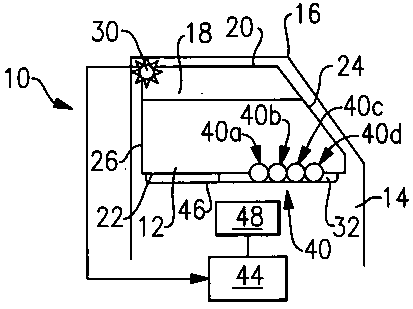
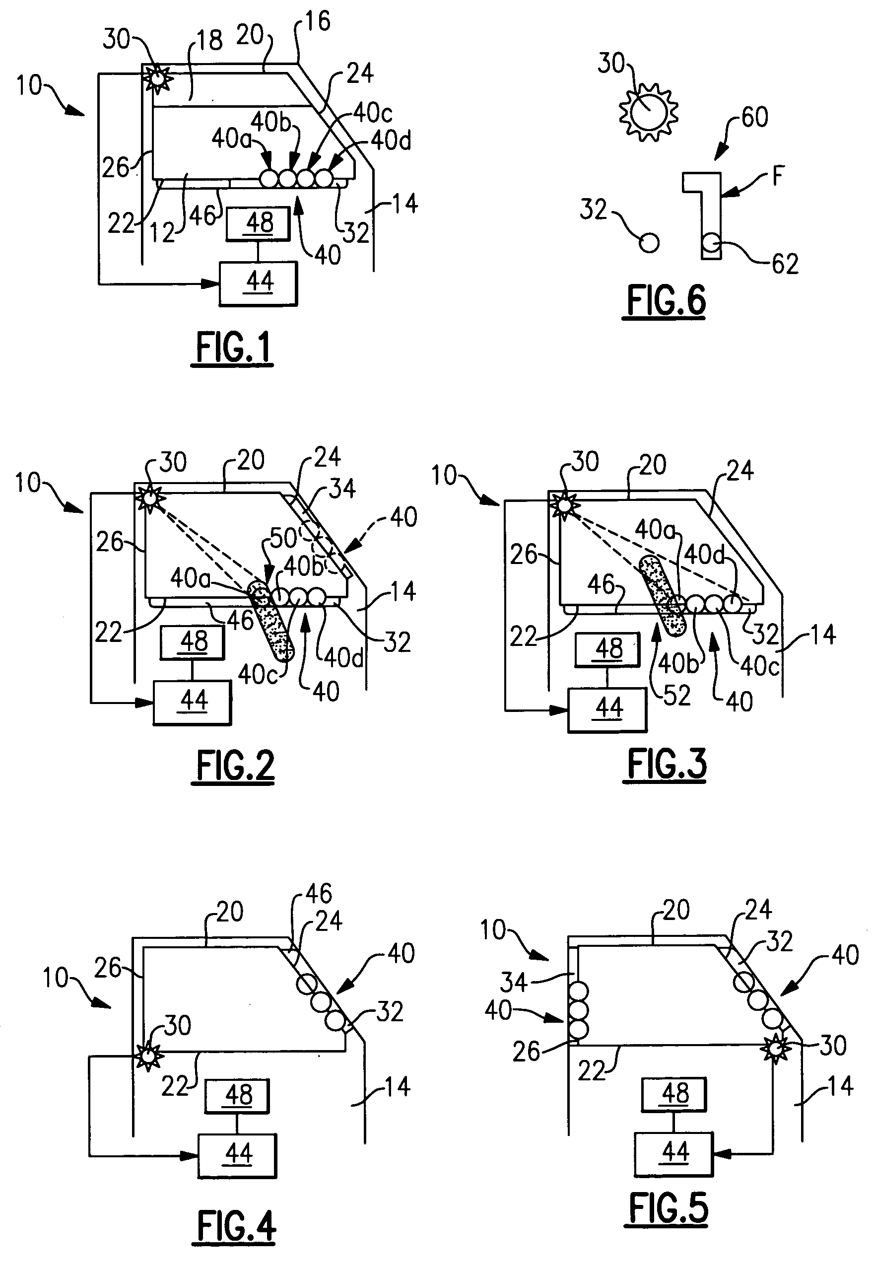
[0017]An anti-pinch control system for a powered vehicle member having a pinching area is shown generally at 10 in FIG. 1. In the example shown, the powered vehicle member comprises a window 12 mounted within a vehicle door 14; however, the powered vehicle member could comprise other vehicle components such as sliding vehicle doors, sunroofs, etc., for example. The pinching area is defined as any area where there is a risk of pinching between the window 12 and a vehicle structure, such as a window frame 16 in this example.

[0018]The vehicle door 14 defines an opening 18 with a plurality of edges. The opening includes at least a top edge 20, a bottom edge 22, a front edge 24, and rear edge 26. In the example shown in the figures, the pinching area is defined as being at least along the top edge 20 and the front edge 24. It should be understood that this is just one example location of a pinching area, and that the location could vary depending on the type of component involved and the...


PUM

PropertyMeasurementUnit
timeaaaaaaaaaa
areaaaaaaaaaaa
movementaaaaaaaaaa

Abstract

An anti-pinch control system is used to identify obstructions in a path of movement for a powered vehicle member, such as a vehicle window for example. A pinching area is identified for the vehicle window and at least one indicium or indicator is mounted to a vehicle structure to be in view of a camera. The indicium is positioned such that no object may pass into the pinching area without also passing between the camera and at least a portion of the indicium. The camera identifies an obstruction when any portion of the indicium is obscured. This indicium includes a plurality of predefined zones, with each zone being associated with an operational function, such as upward window movement, downward window movement, door locking, side mirror movement, etc. This eliminates the need for separate switches to perform each of these functions thereby reducing overall cost for a vehicle door system.

Description

TECHNICAL FIELD[0001]An anti-pinch control utilizes a camera, which cooperates with function control indicator, to control movement of a powered vehicle component.BACKGROUND OF THE INVENTION[0002]Anti-pinch control systems are used to control movement of a powered vehicle component, such as a vehicle window for example, such that an object does not become pinched or caught between the vehicle window and a vehicle structure. Typically, a motor cooperates with a window regulator assembly to move the vehicle window between opened and closed positions. The anti-pinch control system works with the motor and window regulator assembly to stop or reverse window movement once an obstruction is detected.[0003]Many different anti-pinch control systems have been utilized to address this common problem. Many of these systems focus on controlling or monitoring motor characteristics to determine if there is an obstruction. These systems often do not work effectively to provide desired window movem...

Claims


Application Information

Patent Timeline
Patent Type & Authority Applications(United States)
IPC IPC(8): H02P3/00H02P1/00
CPCE05Y2900/55E05Y2800/00Y10T428/24785E05F2015/434E05F15/431
Inventor RHODES, CHRISTOPHER DAVID
Owner ARVINMERITOR LIGHT VEHICLE SYST FRANCE
Why Eureka
Try Eureka