Flat panel display device and frame for the same

Active Publication Date: 2008-03-27
LG ELECTRONICS INC
View PDF9 Cites 13 Cited by
  • Summary
  • Abstract
  • Description
  • Claims
  • Application Information

AI Technical Summary

Benefits of technology

[0014]An even another object of the present invention is to provide a frame for a flat panel display device, which need not to manufacture a new metal mold in the development of a new product anymore, thereby reducing cost and time taken for making metal molds.
[0015]A further object of the present invention is to provide a frame for a flat pane

Problems solved by technology

However, the CRT has become an obstacle to the miniaturization, slimness and lightness of electronic appliances due to the weight and volume thereof.
However, since the frame for flat panel display device according to the related art as described above is integrally formed such that the mount locations of respective elements are fixed, the frames should be manufactured differently depending on the types of display modules and the sizes of the PCBs, resulting that frame sharing cannot be achieved.
As a result, cost and time

Method used


Image

  • Flat panel display device and frame for the same
  • Flat panel display device and frame for the same
  • Flat panel display device and frame for the same

Examples


Embodiment Construction

[0037]Reference will now be made in detail to the preferred embodiments of the present invention, examples of which are illustrated in the accompanying drawings.

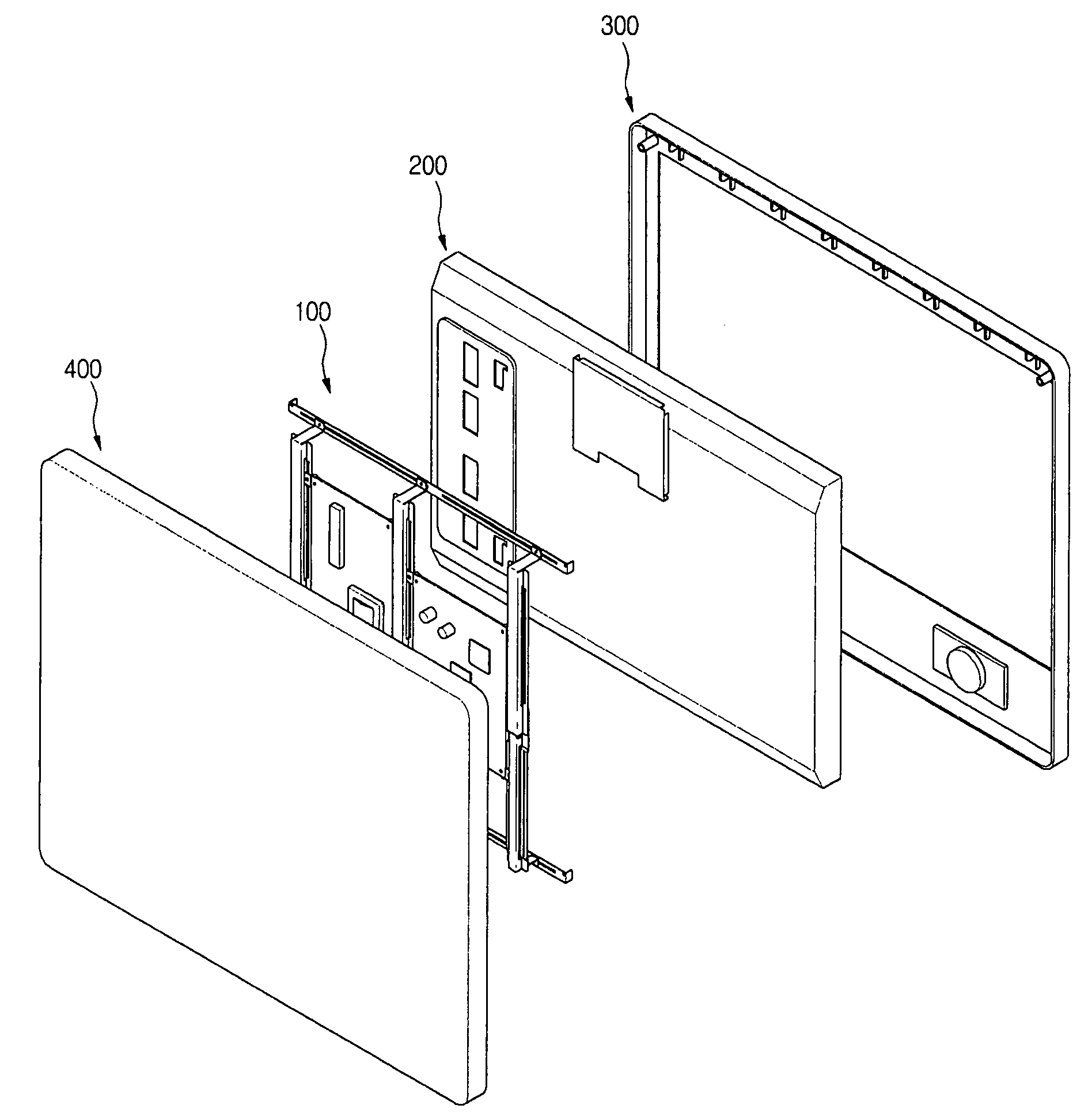
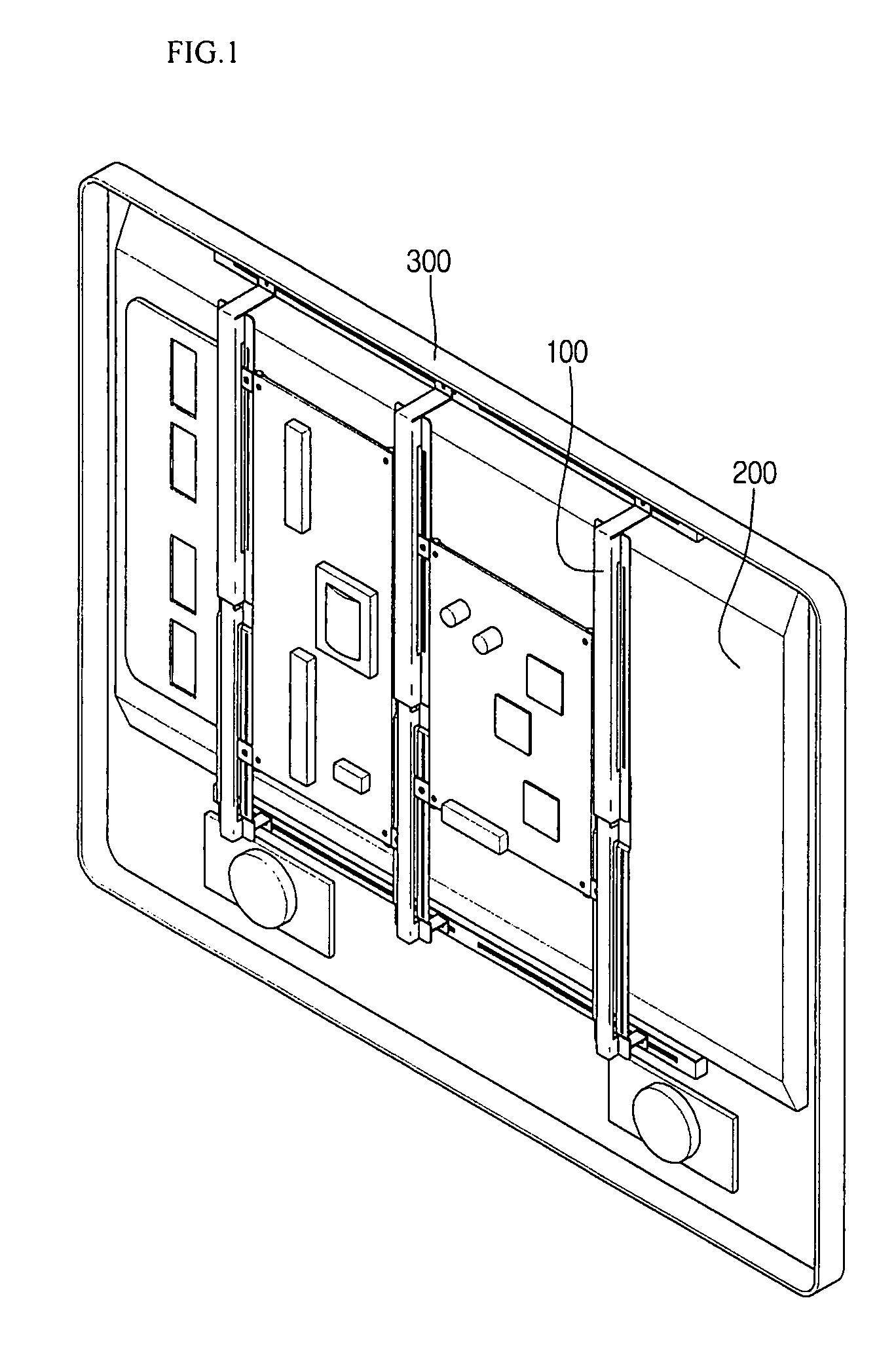
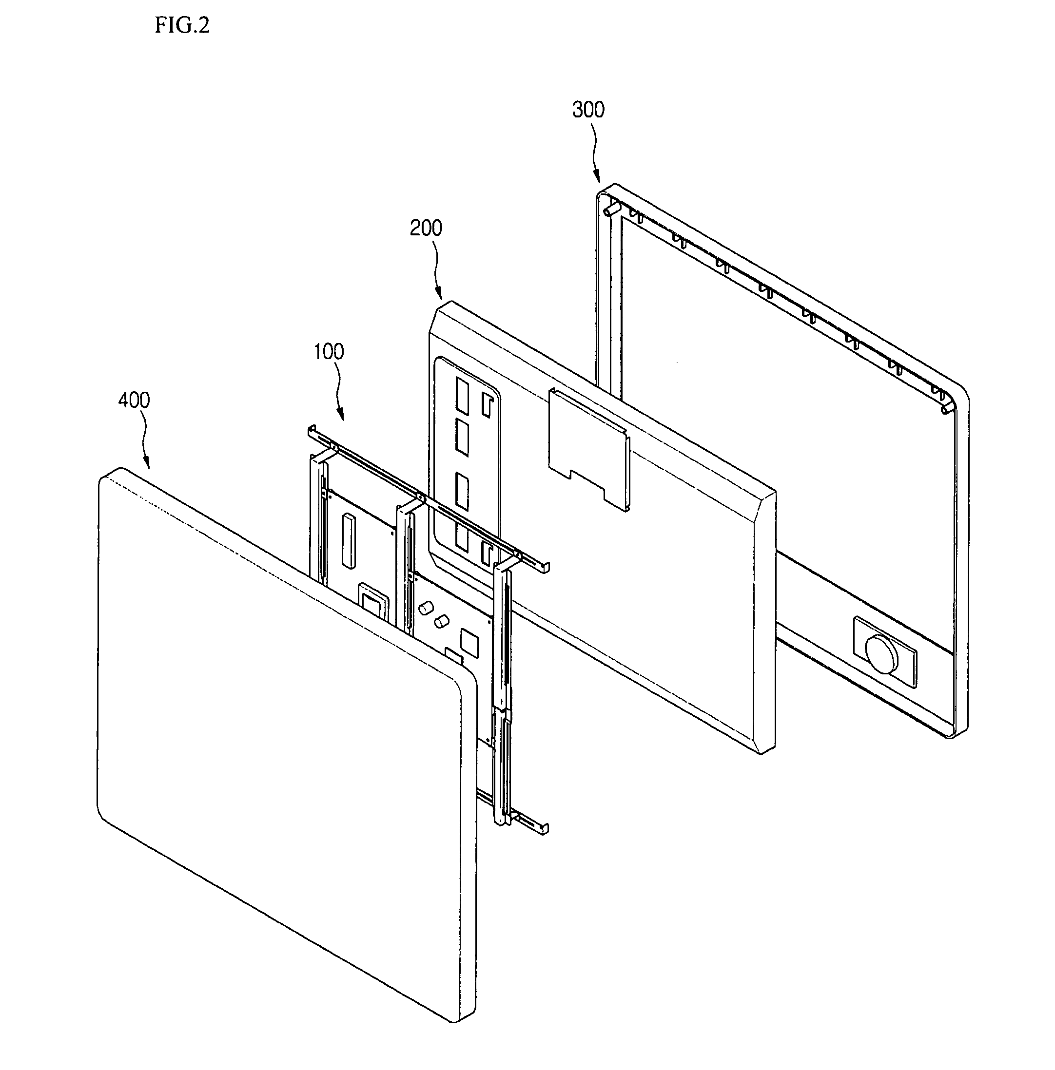
[0038]FIG. 1 is a perspective view showing a coupling structure of a flat panel display device according to the present invention and FIG. 2 is an exploded perspective view showing a structure of a flat panel display device according to the present invention.

[0039]Referring to FIGS. 1 and 2, the flat panel display device includes a front cabinet 300 forming a front shape of the flat panel display device, a display module 200 coupled to a rear side of the front cabinet 300, for implementing an image, a frame assembly 100 coupled with one side of the display module 200, for securing the display module 200 and being mounted with PCB and the like, and a back cover forming a rear shape of the flat panel display device and protecting the display module 200.

[0040]In detail, the front cabinet 300 forms the front shape of the flat pa...


PUM


Abstract

Provided is a frame for flat panel display device so that a single frame can be variably used for various types of display devices. The frame includes: a first frame extending in a first direction and having a coupling section formed in a lengthwise direction of the first frame; a second frame spaced apart by a predetermined distance from the first frame, extending in the first direction and including a coupling section formed in a lengthwise direction of the second frame; and at least one third frame extending in a second direction crossing the first direction and coupled with the coupling sections of the first and second horizontal frames.

Description

BACKGROUND OF THE INVENTION[0001]1. Field of the Invention[0002]The present invention relates to a flat panel display device, and more particularly, to a frame for a flat panel display device to improve the interchangeability between devices.[0003]2. Description of the Related Art[0004]In general, a cathode-ray tube (CRT) has been widely used for a monitor of a device, such as a television, a measuring instrument, a data terminal or the like. However, the CRT has become an obstacle to the miniaturization, slimness and lightness of electronic appliances due to the weight and volume thereof.[0005]To satisfy the increasing requests for the miniaturization, slimness and lightness of electronic appliances, flat display devices, such as a liquid crystal display (LCD) device, a plasma display panel (PDP), and the like which are substitute for the CRT, have been developed and popularized.[0006]Frames for flat panel display devices according to the related art are characterized by each of th...

Claims


Application Information

Patent Timeline
IPC IPC(8): G09G3/20
CPCG02F1/133308H05K5/02G02F2001/133328G02F2001/133325G02F1/133325G02F1/133328H04N5/64
Inventor HONG, CHANG SUNG
Owner LG ELECTRONICS INC
Why Eureka
Try Eureka