Display apparatus, display driving apparatus and method for driving same

a technology of display apparatus and display device, which is applied in the direction of instruments, measurement devices, computing, etc., can solve the problem of varying the brightness of the light emission of the organic el element, and achieve the effect of reducing the risk of light emission

Active Publication Date: 2008-03-27
SOLAS OLED LTD
View PDF7 Cites 233 Cited by
  • Summary
  • Abstract
  • Description
  • Claims
  • Application Information

AI Technical Summary

Problems solved by technology

As a result, there is a risk that brightness during t

Method used


Image

  • Display apparatus, display driving apparatus and method for driving same
  • Display apparatus, display driving apparatus and method for driving same
  • Display apparatus, display driving apparatus and method for driving same

Examples


first embodiment

[0132]The following section will describe the display apparatus 1 of a first embodiment of the invention which displays an image using the above-described display pixel PIX. First, the structure of the display apparatus 1 will be described. As shown in FIG. 9, the display apparatus 1 includes a display zone 11, a selection driver 12, a power source driver 13, a data driver (display driving apparatus) 14, a controller 15, a display signal generation circuit 16, and a display panel 17.

[0133]The display zone 11 includes a plurality of selection lines Ls, a plurality of data lines Ld, and a plurality of display pixels PIX. The respective selection lines Ls are arranged in a horizontal row of the display zone 11 (left-and-right direction in FIG. 9). The respective selection lines Ls are thus parallel to one another. The respective data lines Ld are arranged in a vertical column of the display zone 11 (up-and-down direction in FIG. 9). The respective data lines Ld are thus parallel to one...

second embodiment

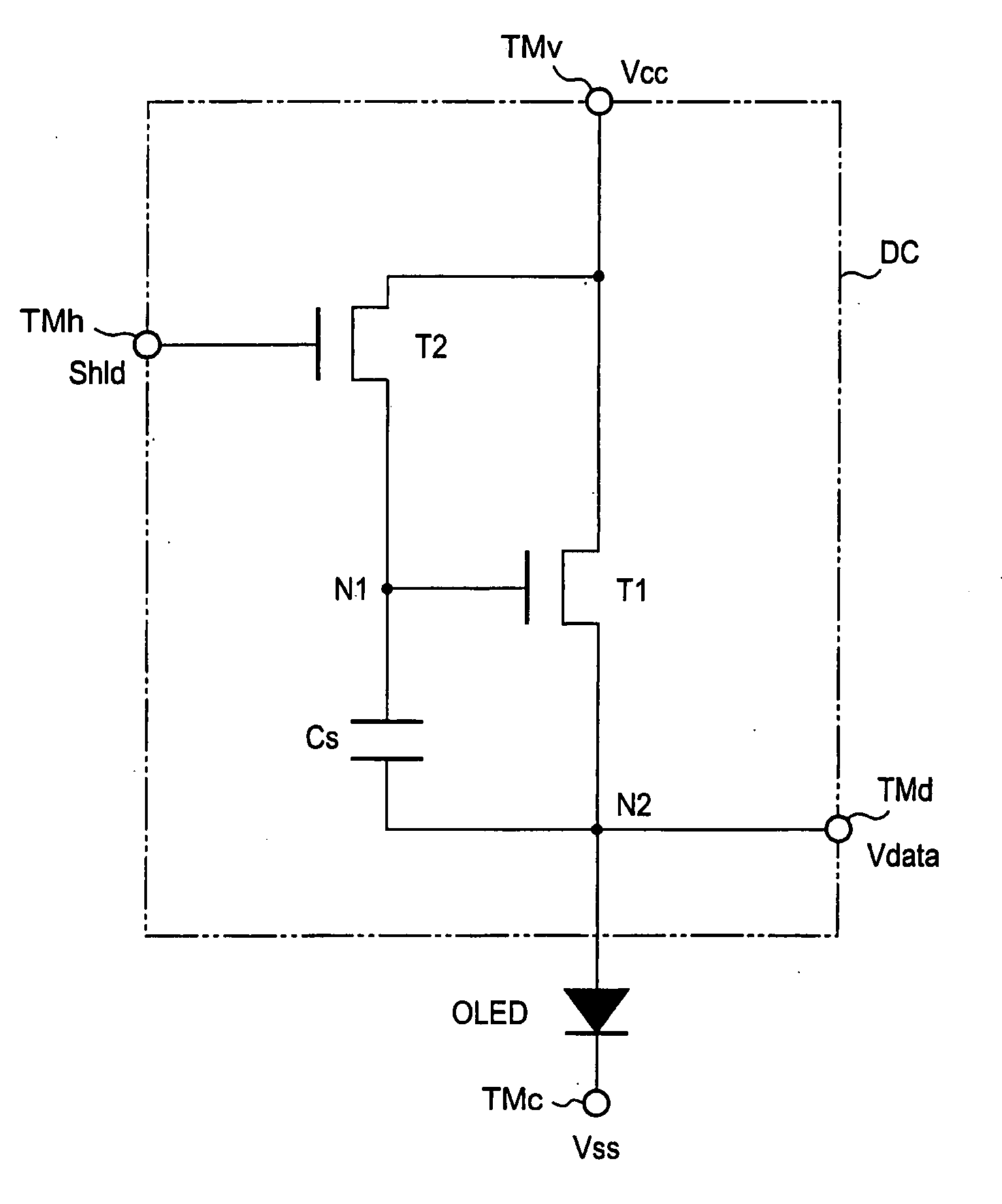
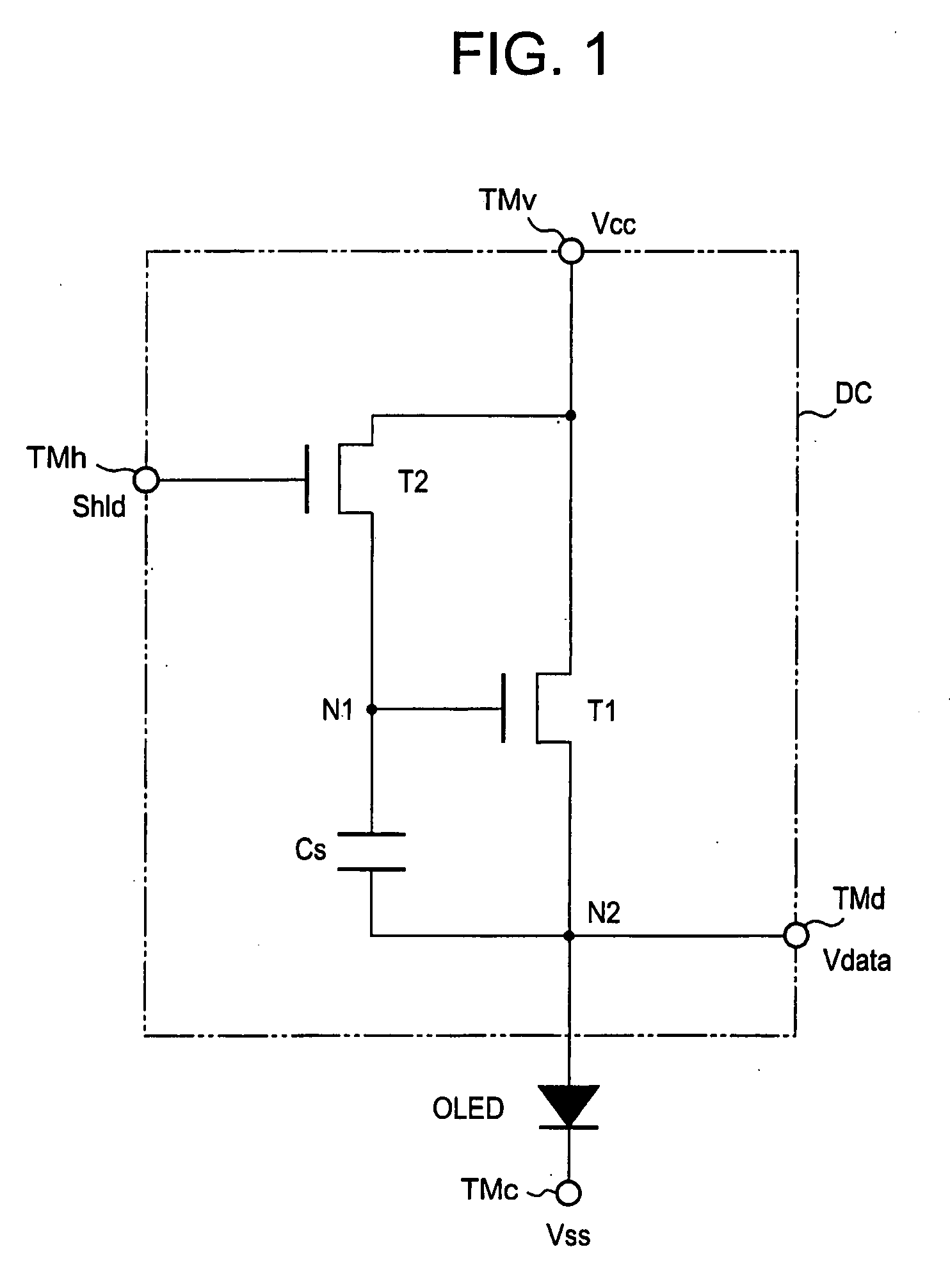
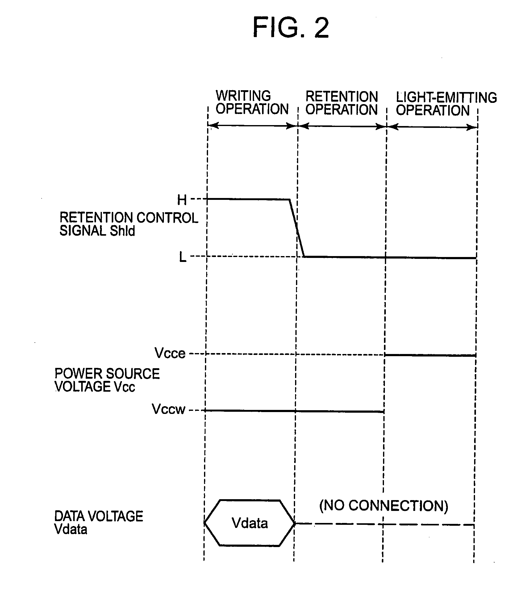
[0252]In the voltage specification-type gradation level control method according to the first embodiment, the original gradation level voltage Vorg is compensated based on the difference voltage ΔVref between the respective reference voltages Vref(t1) and Vref(t2) to generate the compensated gradation level voltage Vpix. This compensated gradation level voltage Vpix is applied to the respective display pixels PIX. The gradation level control method shown in the first embodiment is based on an assumption that the effect of the capacity component parasitic on the display pixel PIX can be sufficiently suppressed by the capacitor Cs connected between the gate and the source of the driving transistor Tr13. This method is also based on an assumption that, even when the power source voltage Vcc is switched from the writing level to the light-emitting level, there is no variation in the writing voltage retained in the capacitor Cs.

[0253]However, a mobile electronic apparatus such as a mobil...


PUM


Abstract

A light-emitting element capable of emitting light having a preferred gradation level depending on display data. During a precharge period, a data driver applies a precharge voltage to a capacitor via a data line. After the application of the precharge voltage, a voltage converter reads a first reference voltage Vref(t1) and a second reference voltage Vref(t2) to generate a compensation voltage based on a difference between the respective reference voltages. Based on the compensation voltage, a voltage calculator compensates an original gradation level voltage Vorg having a value in accordance with display data generated by a gradation level voltage generator. The voltage calculator generates a compensated gradation level voltage Vpix corresponding to a variation amount of an element characteristic for a transistor Tr13 for driving light emission to apply the compensated gradation level voltage Vpix to a data line Ld.

Description

CROSS REFERENCE TO RELATED APPLICATIONS[0001]This application is based on Japanese Patent Application No. 2006-260650 filed on Sep. 26, 2006, and Japanese Patent Application No. 2007-083360 filed on Mar. 28, 2007, the entire contents of both of which are incorporated herein by reference.BACKGROUND OF THE INVENTION[0002]1. Field of the Invention[0003]The present invention relates to a display driving apparatus and a method for driving a display driving apparatus as well as a display apparatus and a method for driving a display apparatus.[0004]2. Description of the Related Art[0005]There exists a display apparatus that includes a display panel in which current driving-type light-emitting elements (e.g., organic electroluminescence (EL) elements, inorganic EL elements, light-emitting diodes (LED)) are arranged in a matrix manner.[0006]For example, Unexamined Japanese Patent Application KOKAI Publication No. H8-330600 discloses an active matrix-type driving display apparatus that is cur...

Claims


Application Information

Patent Timeline
IPC IPC(8): G09G5/00G09G3/32
CPCG09G3/3233G09G2320/043G09G2320/0233G01R19/00G09G3/20G09G3/30G09G3/32
Inventor OGURA, JUN
Owner SOLAS OLED LTD
Why Eureka
Try Eureka