Display control system for spatial light modulators

a control system and light modulator technology, applied in the field of display control system using spatial light modulator, can solve the problems of limited image display quality, adverse effects on image quality, limited image quality, etc., and achieve the effect of reducing the maximum output brightness, reducing the contrast, and high accuracy outpu

Inactive Publication Date: 2008-03-27
SILICON QUEST KABUSHIKI KAISHA +1
View PDF11 Cites 2 Cited by
  • Summary
  • Abstract
  • Description
  • Claims
  • Application Information

AI Technical Summary

Benefits of technology

[0022] According to the aforementioned aspect, a use of two manners of control methods, i.e., one for outputting gray scales by means of an integral in a temporal axis by using a binary value of the ON and OFF of the SLM and another for outputting an intermediate gray scale by outputting neither the ON nor OFF, that is, an intermediate level, makes it possible to obtain an effi

Problems solved by technology

Even though there have been significant advances of the technologies implementing an electromechanical mirror device as an SLM in recent years, there are still limitations and difficulties when it is employed to provide a high quality image.
Specifically, when the images are digitally controlled, the image quality is adversely affected due to the fact that the images are not displayed with a sufficient number of gray scales.
The quality of an image display is limited due to the limited number of gray scales.
Since the mirror is controlled to operate in an either ON or OFF state, the conventional image display apparatuses have no way of providing a pulse width to control the mirror that is shorter than the control duration allowable according to the LSB.
The limited gray scale leads to a degradation of the image.
That leads to the degradations of image qualities.
The artifacts are caused by a technical limitation that the digitally controlled image does not obtain a sufficient number of the gray scale, i.e. the levels of the quantity of light.
The mirrors produced by applying the CMOS technologies probably is not appropriate for operating the mirror at such a high range of voltages, and therefore the DMOS mirror devices may be required.
Conventional mirror controls are theref

Method used


Image

  • Display control system for spatial light modulators
  • Display control system for spatial light modulators
  • Display control system for spatial light modulators

Examples


Embodiment Construction

[0049] The following is a description of the preferred embodiment of the present invention by referring to the accompanying drawings.

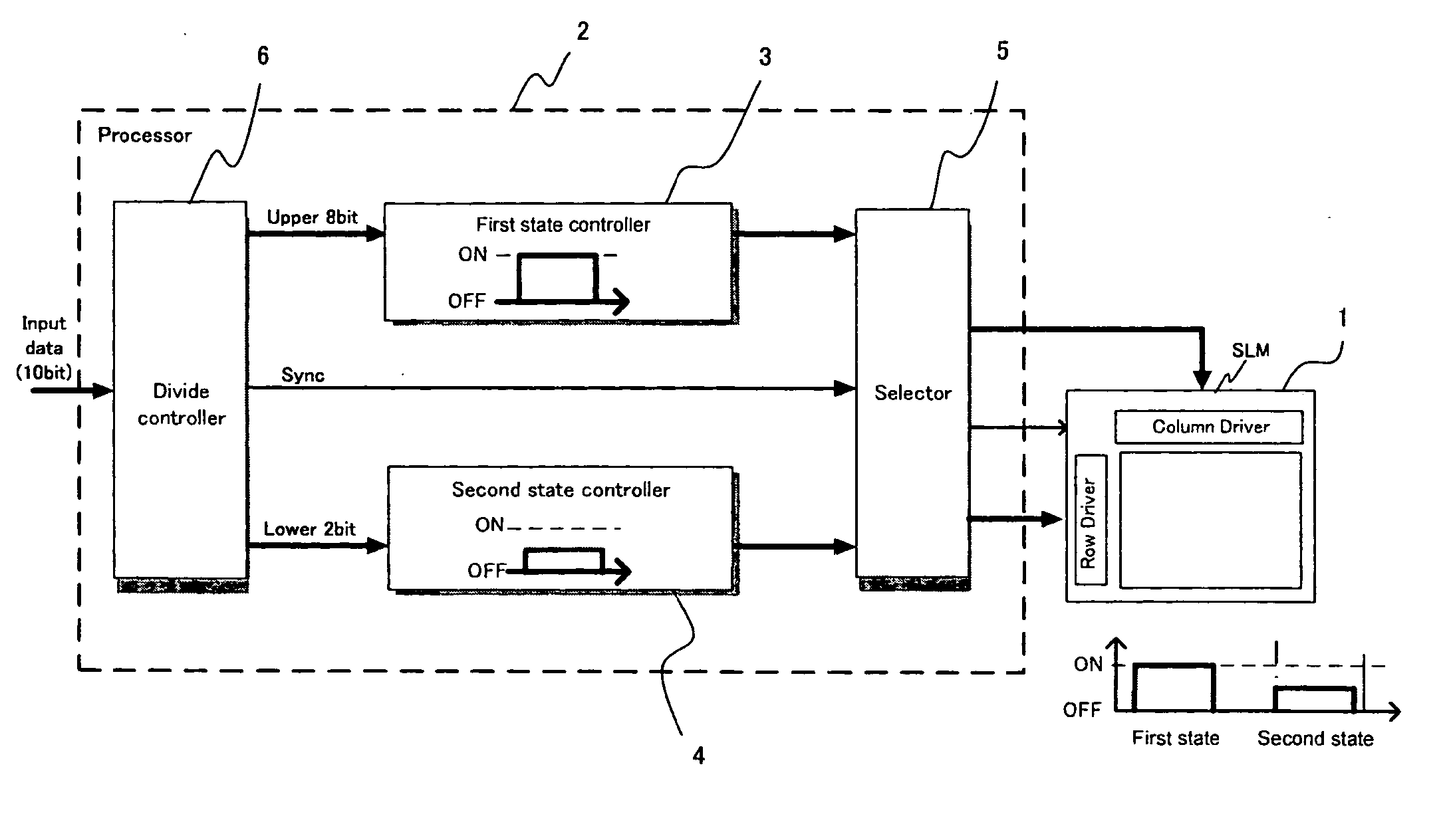
[0050]FIG. 3 is a functional block diagram for illustrating the major functions carried out by a display control system according to a preferred embodiment. As shown in FIG. 3, the display control system comprises a spatial light modulator (SLM) 1 that includes a plurality of pixel elements arranged in an array configuration with rows and columns. The display control system further includes a processor 2 for controlling the SLM 1 in accordance with input data.

[0051] The SLM 1 modulates an incident light from a light source (not shown) under the control of the processor 2. A portion of the light modulated and reflected by the SLM 1 is projected to a projection light path to enter into a projection optical system and then for displaying an image on a screen (not shown).

[0052] The processor 2 includes a first state controller, e.g., a first control uni...


PUM


Abstract

A display control system, comprises: a spatial light modulator (SLM) constituted by a plurality of pixel elements placed in array; a first control unit for controlling each of the plurality of pixel elements under a state of ON or OFF; a second control unit for controlling each of the plurality of pixel elements under a state other than the ON or OFF states; a control changeover unit for dividing one frame period, for each pixel element of the plurality thereof, into a period of the first control unit controlling and that of the second control unit controlling, and also changing over between a control of the first control unit and that of the second control unit for each pixel element of the plurality thereof; and a data division unit for dividing input data to each of the plurality of pixel elements into first control unit-use data, which is input to the first control unit, and second control unit-use data which is input to the second control unit in accordance with the content of the present input data.

Description

[0001] This application is a Non-provisional application of a Provisional Application 60 / 841,125 filed on Aug. 30, 2006. The Provisional Application 60 / 841,125 is a Continuation in Part (CIP) application of a pending U.S. patent application Ser. No. 11 / 121,543 filed on May 4, 2005. The application Ser. No. 11 / 121,543 is a Continuation in part (CIP) application of three previously filed applications. These three applications are Ser. No. 10 / 698,620 filed on Nov. 1, 2003, Ser. No. 10 / 699,140 filed on Nov. 1, 2003, and Ser. No. 10 / 699,143 filed on Nov. 1, 2003 by one of the Applicants of this patent application. The disclosures made in these patent applications are hereby incorporated by reference in this patent application.BACKGROUND OF THE INVENTION [0002] 1. Field of the Invention [0003] The present invention relates to a display control system using a spatial light modulator. More particularly, this invention relates to a control system to improve the display image quality. [0004] ...

Claims


Application Information

Patent Timeline
IPC IPC(8): H04N5/74
CPCG02B26/0833G09G3/2011G09G3/2022H04N9/312G09G3/346H04N5/7458G09G3/2081
Inventor NISHINO, HIROKAZUARAI, KAZUMAISHII, FUSAOMAEDA, YOSHIHIROENDO, TARO
Owner SILICON QUEST KABUSHIKI KAISHA
Why Eureka
Try Eureka