Vibration reduction apparatus, optical equipment and a method of manufacturing the vibration reduction apparatus

a technology of vibration reduction and optical equipment, which is applied in the field optical equipment, and a manufacturing method of vibration reduction apparatus, can solve the problems of reducing the accuracy of blur correction, and achieve the effect of high blur correction precision and high blur precision

Inactive Publication Date: 2008-03-27
NIKON CORP
View PDF0 Cites 18 Cited by
  • Summary
  • Abstract
  • Description
  • Claims
  • Application Information

AI Technical Summary

Benefits of technology

[0047]According to the above configuration, a vibration reduction apparatus with high blur correction precision, opt...

Problems solved by technology

Thus the wiring substrate might become resistance for relative movement between the...

Method used


Image

  • Vibration reduction apparatus, optical equipment and a method of manufacturing the vibration reduction apparatus
  • Vibration reduction apparatus, optical equipment and a method of manufacturing the vibration reduction apparatus
  • Vibration reduction apparatus, optical equipment and a method of manufacturing the vibration reduction apparatus

Examples


Embodiment Construction

[0060]Hereafter, an embodiment of the present invention is described in more detail with reference to the drawings. The following embodiment is described by taking a camera system as optical equipment comprising a vibration reduction apparatus, as an example.

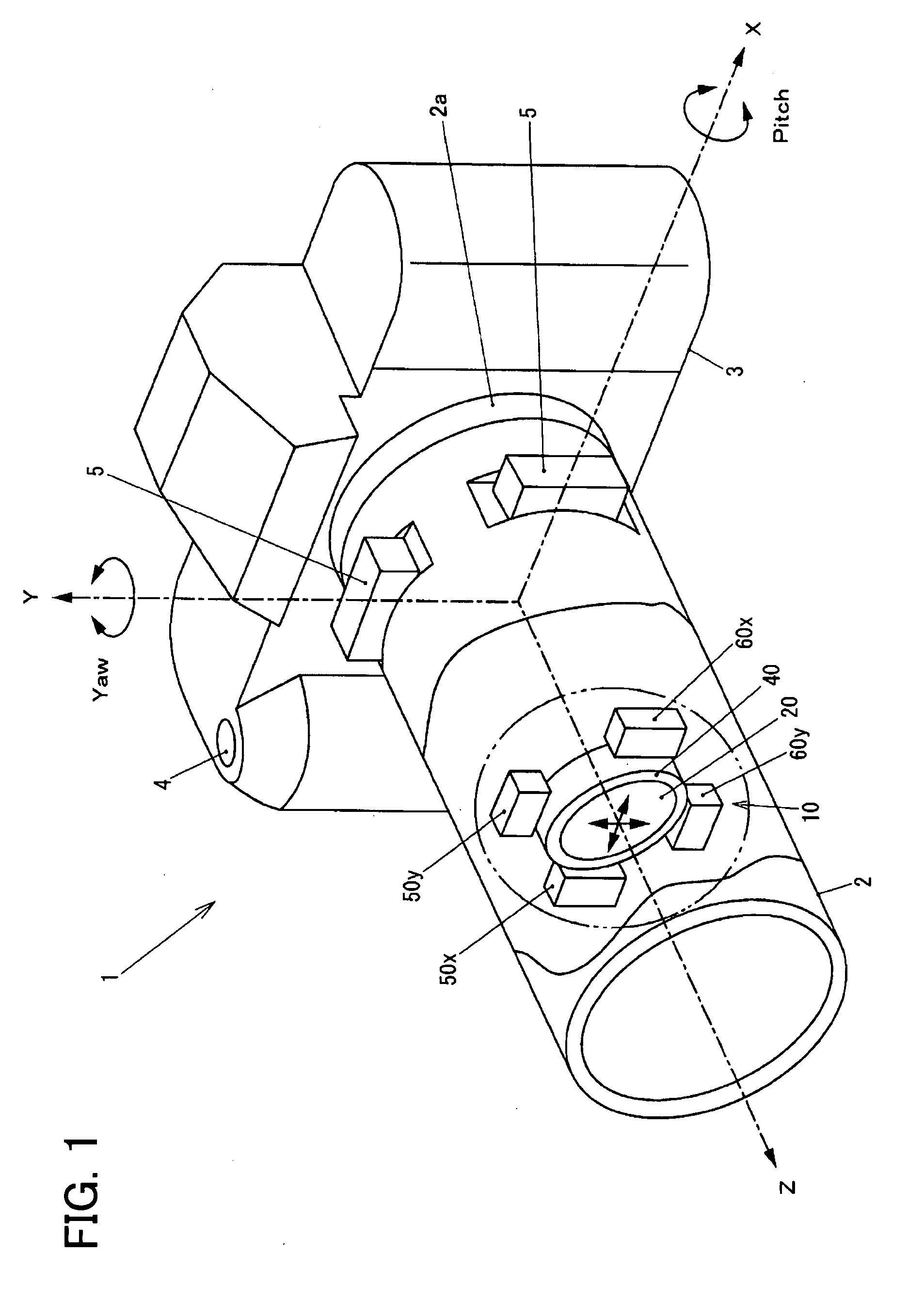
[0061]FIG. 1 is a perspective view showing the camera system of the embodiment of the present invention. In FIG. 1, a camera system 1 of the embodiment has an interchangeable lens 2 and a camera body 3.

[0062]The interchangeable lens 2 has a cylindrical shape as a whole, and the end at the image side in an optical axis direction is secured to the camera body 3 detachably through a mounting portion 2a. The interchangeable lens 2 is provided with a vibration reduction apparatus 10 and a plurality of lens unit arranged on an optical axis Z (lens unit other than a blur correcting lens 20 are not shown in the figure).

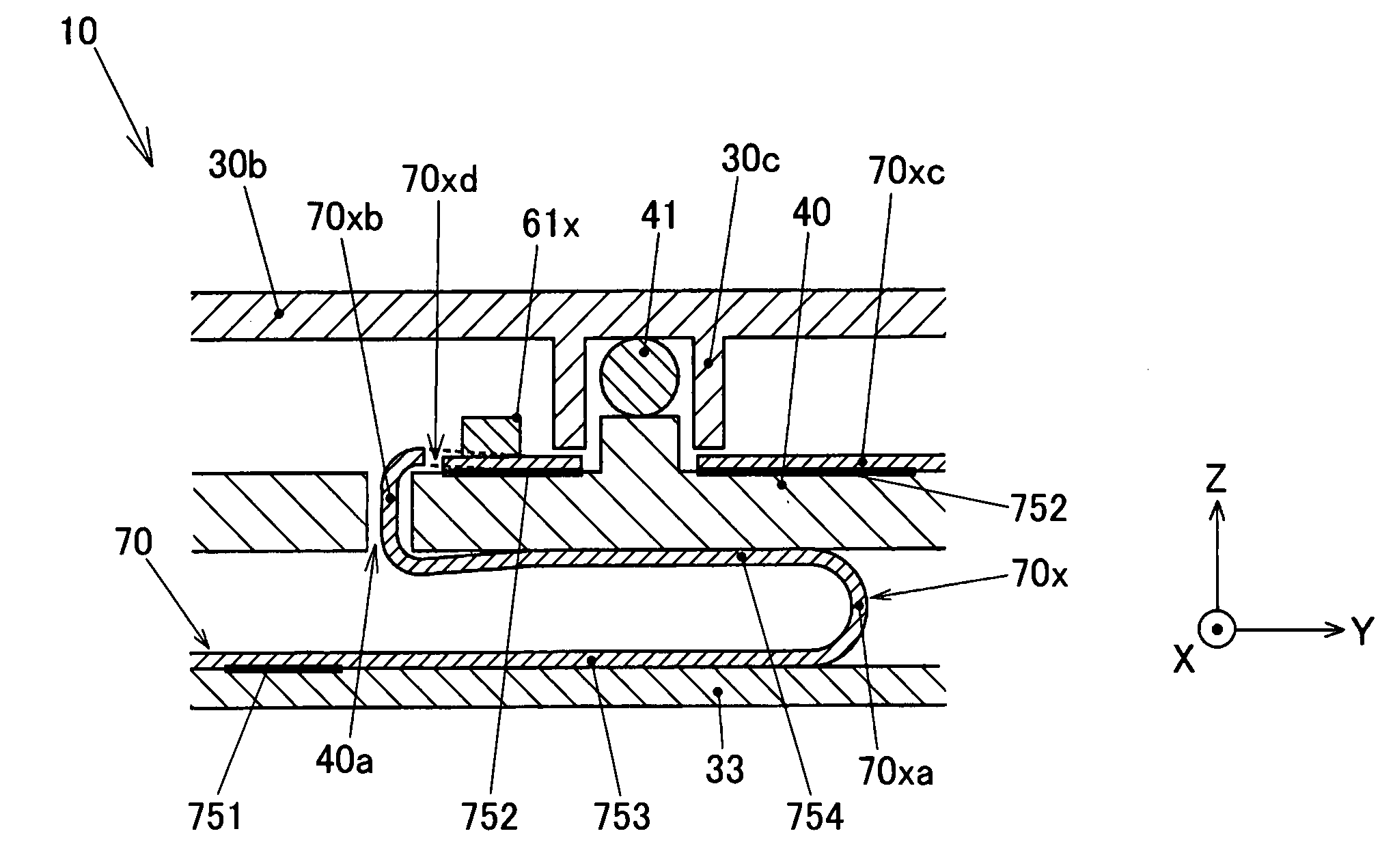
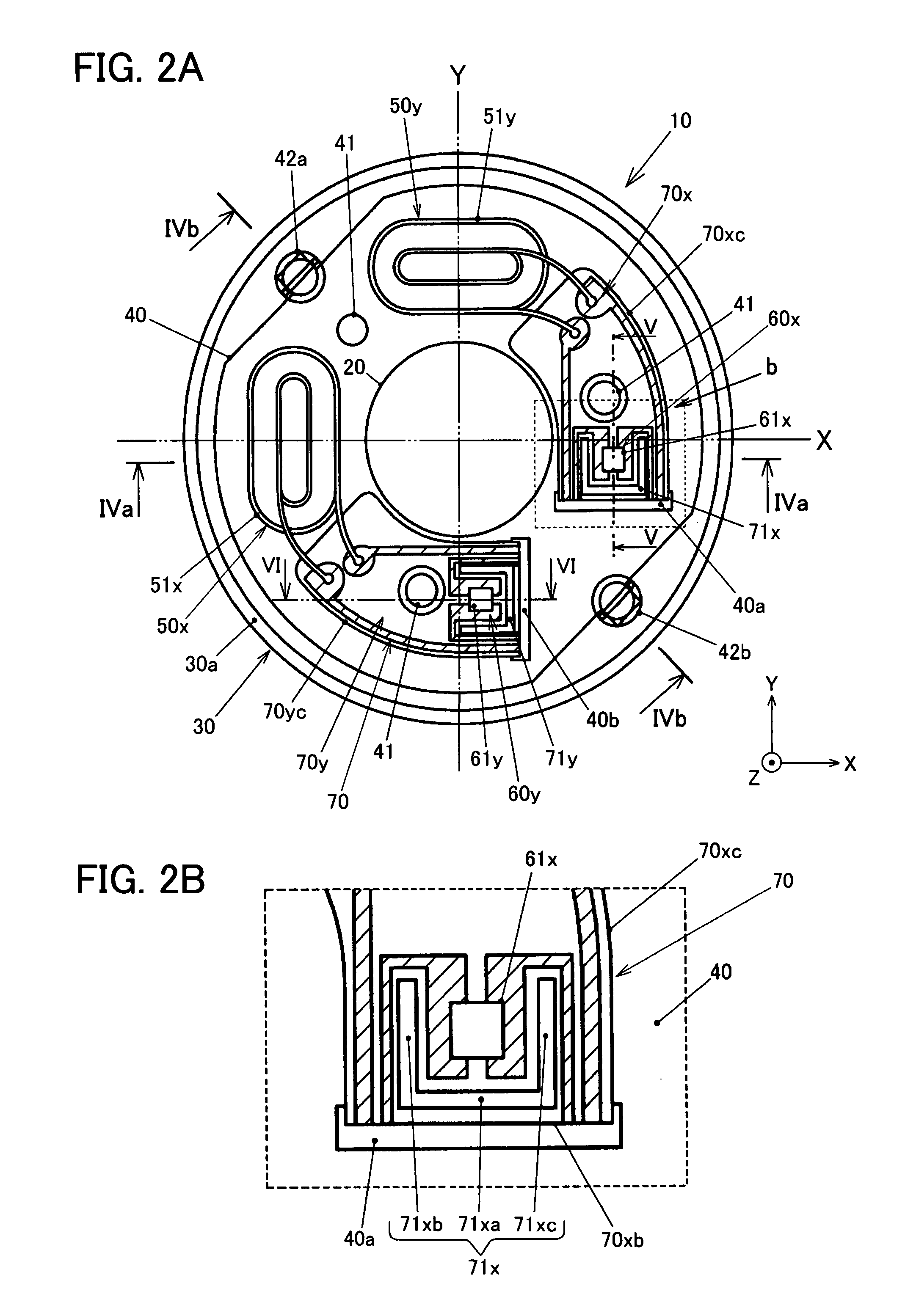
[0063]FIGS. 2A, 2B are plan views showing the vibration reduction apparatus provided in the camera system of FIG. 1, vi...


PUM


Abstract

To provide a vibration reduction apparatus with improved blur correcting precision, an optical equipment and a method of manufacturing a vibration reduction apparatus with improved blur correcting precision. A vibration reduction apparatus comprising: a first member and a second member disposed to be opposite to each other and to be movable relative to each other when blur is correcting; and a wiring member that exerts a force between the first member and the second member along a direction that intersects with a direction of the relative movement of the first member and the second member.

Description

[0001]The disclosure of the following priority application is herein incorporated by reference: Japanese Patent Applications No. 2006-262411 and No. 2006-262433 filed on Sep. 27, 2006.BACKGROUND OF THE INVENTION[0002]1. Field of the Invention[0003]The present invention relates to a vibration reduction apparatus, optical equipment, and a method of manufacturing the vibration reduction apparatus.[0004]2. Description of Related Art[0005]The vibration reduction apparatus provided in optical equipment such as a camera is known. The conventional vibration reduction apparatus has a lens frame hold a blur correcting lens therein and movable relative to a fixing member. The lens frame moves relative to the fixing member during blur correcting. The conventional vibration reduction apparatus comprises a flexible wiring substrate, that supplies power to an actuator and a position detecting sensor or the like, which is mounted on the lens frame. Thus the wiring substrate might become resistance ...

Claims


Application Information

Patent Timeline
IPC IPC(8): G02B27/64
CPCG02B27/646G03B5/00H04N5/23287H04N5/2254G03B2205/0007H04N23/55H04N23/687
Inventor OSAKA, SEIJIMIYAMOTO, HIDENORI
Owner NIKON CORP
Why Eureka
Try Eureka