
Packet forwarding apparatus with function of limiting the number of user terminals to be connected to ISP

a forwarding apparatus and user terminal technology, applied in electrical apparatus, digital transmission, data switching networks, etc., can solve the problems of not being able to guarantee the identification information of the access line, and the load resulting from limiting connected user terminals is localized to the management server, so as to reduce the concentration of load

Inactive Publication Date: 2008-03-27
HITACHI LTD
View PDF4 Cites 10 Cited by
  • Summary
  • Abstract
  • Description
  • Claims
  • Application Information

AI Technical Summary

Benefits of technology

[0019] An object of the present invention is to provide a packet forwarding apparatus (L2SW) capable of limiting the number of assigned IP addresses and the number of PPPoE sessions for each user by reducing a load on the management server of an ISP.
[0025] In accordance with the present invention, since the packet forwarding apparatus (L2SW) disposed between the management server of an ISP and a plurality of user terminals can alone limit the number of assigned IP addresses and the number of connected sessions for each access line, it becomes possible to reduce the concentration of a load on the management server of the ISP.

Problems solved by technology

Because the technique (1) assumes the association between the L2SW and the management server, it becomes useless in the case where the L2SW is operated by a business entity independent of the ISP to which the management server belongs and an associative operation between the L2SW and the management server, e.g., the notification of the identification information of the access line cannot be guaranteed.
In addition, each of the conventional technique (1) and (2) has the problem that a load resulting froma processing for limiting connected user terminals is localized to the management server since a plurality of L2SWs are connected to the management server of the ISP and the management server receives session connection requests and IP address assignment requests from a large number of user terminals via the L2SWs.

Method used


Image

  • Packet forwarding apparatus with function of limiting the number of user terminals to be connected to ISP
  • Packet forwarding apparatus with function of limiting the number of user terminals to be connected to ISP
  • Packet forwarding apparatus with function of limiting the number of user terminals to be connected to ISP

Examples


embodiment 1

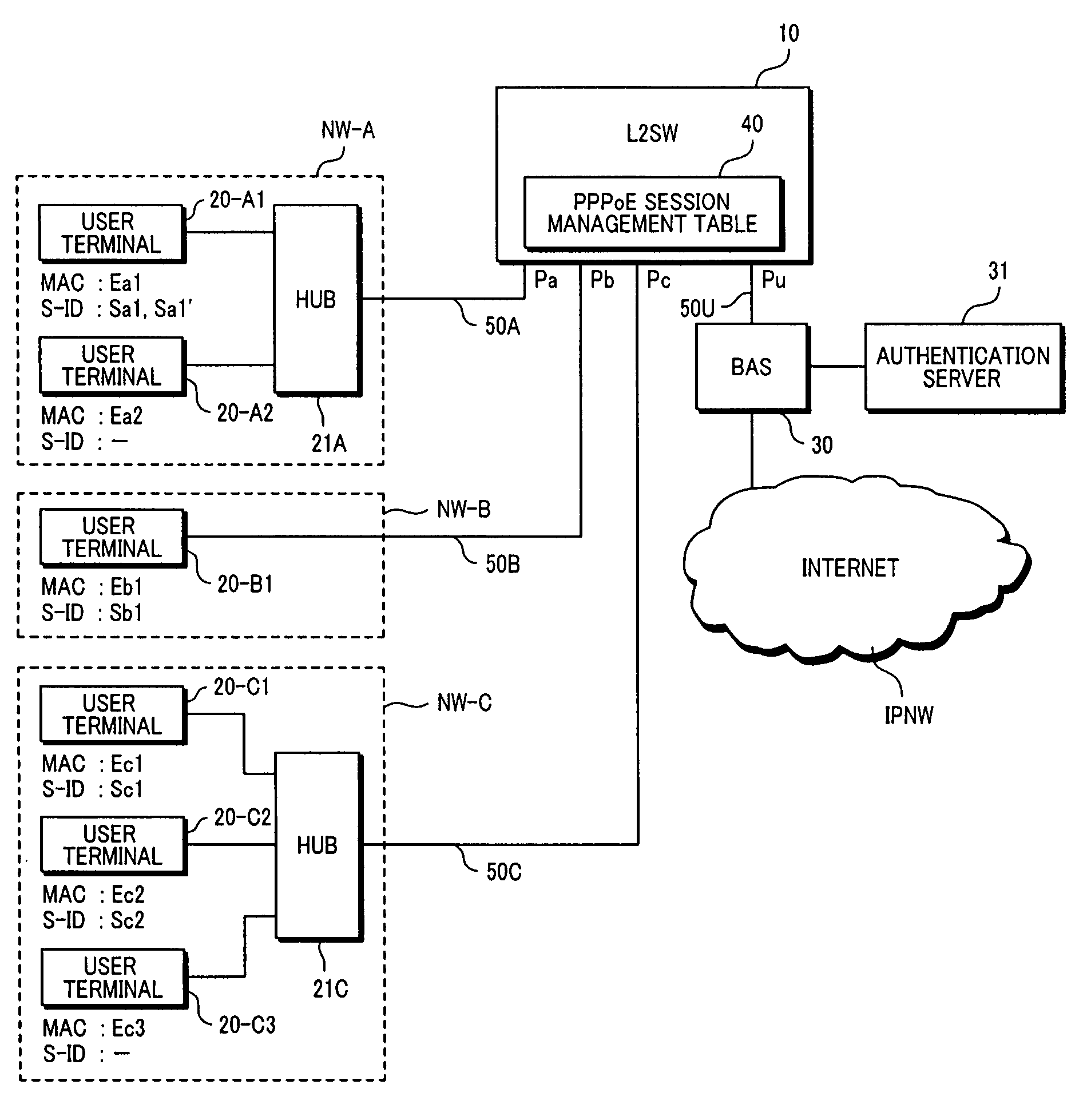
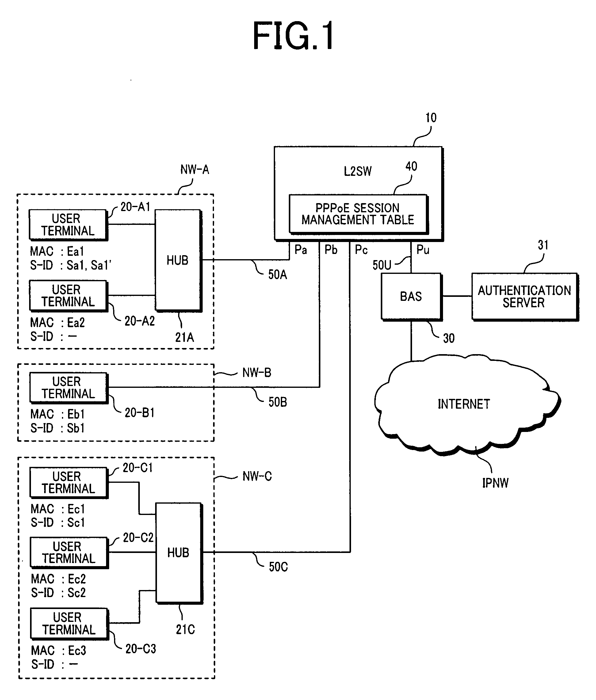
[0047]FIG. 1 shows a first embodiment of a network configuration including a packet forwarding apparatus (Layer-2 switch: L2SW) 10 according to the present invention.

[0048] The network shown here is comprised of a plurality of user networks NW (NW-A, NW-B, NW-C, . . . ) connected to the L2SW 10 and the Internet IPNW. The L2SW 10 is connected to the Internet IPNW via a BAS (Broadband Access Server) 30 managed by an ISP. The BAS 30 is connected to an authentication server 31 for authenticating a user as an Internet connection requester. Alternatively, the function of the authentication server 31 may be installed in the BAS 30.

[0049] The user networks NW are subdivided into those in which a plurality of user terminals 20 (20-A1, 20-A2, and 20-C1 to 20-C3) are connected to the L2SW 10 via home hubs 21 (21A and 21C), such as NW-A and NW-C, and those in which a user terminal 20-B1 is connected directly to the L2SW 10 via an access line 50B, such as NW-B.

[0050] It is also possible, e.g....

embodiment 2

[0104]FIG. 10 shows a second embodiment of the network configuration including the packet forwarding apparatus (Layer-2 switch: L2SW) 10 according to the present invention. As contrast with FIG. 1, a feature of the network according to the present embodiment resides in that L2SW 10 is provided with an IP address management table 70 and connected to the Internet IPNW via a router 32.

[0105] The router 32 has the function of a DHCP server for performing the assignment / release of an IP address with an expiration time with respect to the user terminal 20 in accordance with the DHCP (Dynamic Host Configuration Protocol). Alternatively, it is also possible to place a DHCP relay agent at the position of the router 32. In this case, a DHCP server is prepared in addition to the router 32 (DHCP relay agent) so that any of the user terminals 20 and the DHCP server communicate DHCP packets via the router 32.

[0106] In the present embodiment, the L2SW 10 limits the number of IP addresses to be a...


PUM


Abstract

A packet forwarding apparatus for connecting a plurality of user terminals to an ISP management server has a management table indicating the relationship between a connection port identifier and specific header information in association with the MAC address of each of the user terminals so that, in a communication protocol procedure executed between each of the user terminals and the ISP management server prior to communication with a wide-area network, the packet forwarding apparatus discards a packet for the user terminal when it is determined that the specific header information cannot be assigned to the user terminal based on the management table.

Description

CROSS REFERENCE TO RELATED APPLICATIONS [0001] This application is a Continuation of nonprovisional U.S. application Ser. No. 11 / 362,218 filed on Feb. 27, 2006, which claims the priority of Japanese Application No. 2005-357714, filed on Dec. 12, 2005. Priority is claimed based on U.S. application Ser. No. 11 / 362,218 filed on Feb. 27, 2006, which claims the priority of Japanese Application No. 2005-357714, filed on Dec. 12, 2005, all of which is incorporated by reference.BACKGROUND OF THE INVENTION [0002] (1) Field of the Invention [0003] The present invention relates to a packet forwarding apparatus and, more particularly, to a packet forwarding apparatus with the function of limiting the number of user terminals to be connected to an ISP (Internet Service Provider) in an access network connected to the Internet as a wide-area network. [0004] (2) Description of Related Art [0005] With the tendency toward a broader-band access line from a user terminal to the Internet, and with the p...

Claims


Application Information

Patent Timeline
Patent Type & Authority Applications(United States)
IPC IPC(8): H04L12/56H04L12/44
CPCH04L12/2856H04L12/2859H04L12/2872H04L29/12839H04L69/324H04L61/106H04L61/6022H04L69/168H04L41/0226H04L2101/622
Inventor TSUGE, MUNETOSHINAKAMURA, RYOSAITO, TOSHIYUKISHINOHARA, YASUNARI
Owner HITACHI LTD
Learn More