Personal breathalyzer having digital circuitry

a breathalyzer and digital circuit technology, applied in the direction of respiratory organ evaluation, diagnostic recording/measuring, instruments, etc., can solve the problems of high accuracy, difficult and expensive to achieve specificity and accuracy at low breath alcohol concentration levels, voltage curve which goes to the peak and remains on a high plateau for an unacceptably long tim

Inactive Publication Date: 2008-04-03
HONOR TONE +1
View PDF0 Cites 29 Cited by
  • Summary
  • Abstract
  • Description
  • Claims
  • Application Information

AI Technical Summary

Problems solved by technology

This IR technology has the advantage of making real-time measurements; however, it is particularly difficult and expensive to achieve specificity and accuracy at low breath alcohol concentration levels.
Although this method has proven to have high accuracy levels, there are a number of problems.
In order to produce a high peak, it is customary to put across the output terminals of the fuel cell a high external resistance, on the order of a thousand ohms, but the use of such a high resistance produces a voltage curve which goes to the peak and remains on a high plateau for an unacceptably long time.
However, it is still necessary to let the cell recover, because if the short is removed in less than one-half to two minutes after the initial peak time, for example, the voltage creeps up.
Presently, the cell is replaced when it peaks too slowly or when the output at the peak declines beyond practical re-calibration, or when the background voltage begins creeping excessively after the short is removed from the cell terminals.
Systems employing this method were also cost prohibitive for many applications.
One reason for the high cost associated with the fuel cell techniques is that the method requires that the breath sample be of a determinable volume.
The incorporation of such components within an electronic device necessarily increases the costs associated with the device.
Although this method provides a low cost device, instruments incorporating this method have proved to have poor accuracy because of the need to hold input voltage signals to the electronic components of the device at constant, steady, regulated levels.

Method used


Image

  • Personal breathalyzer having digital circuitry
  • Personal breathalyzer having digital circuitry
  • Personal breathalyzer having digital circuitry

Examples


Embodiment Construction

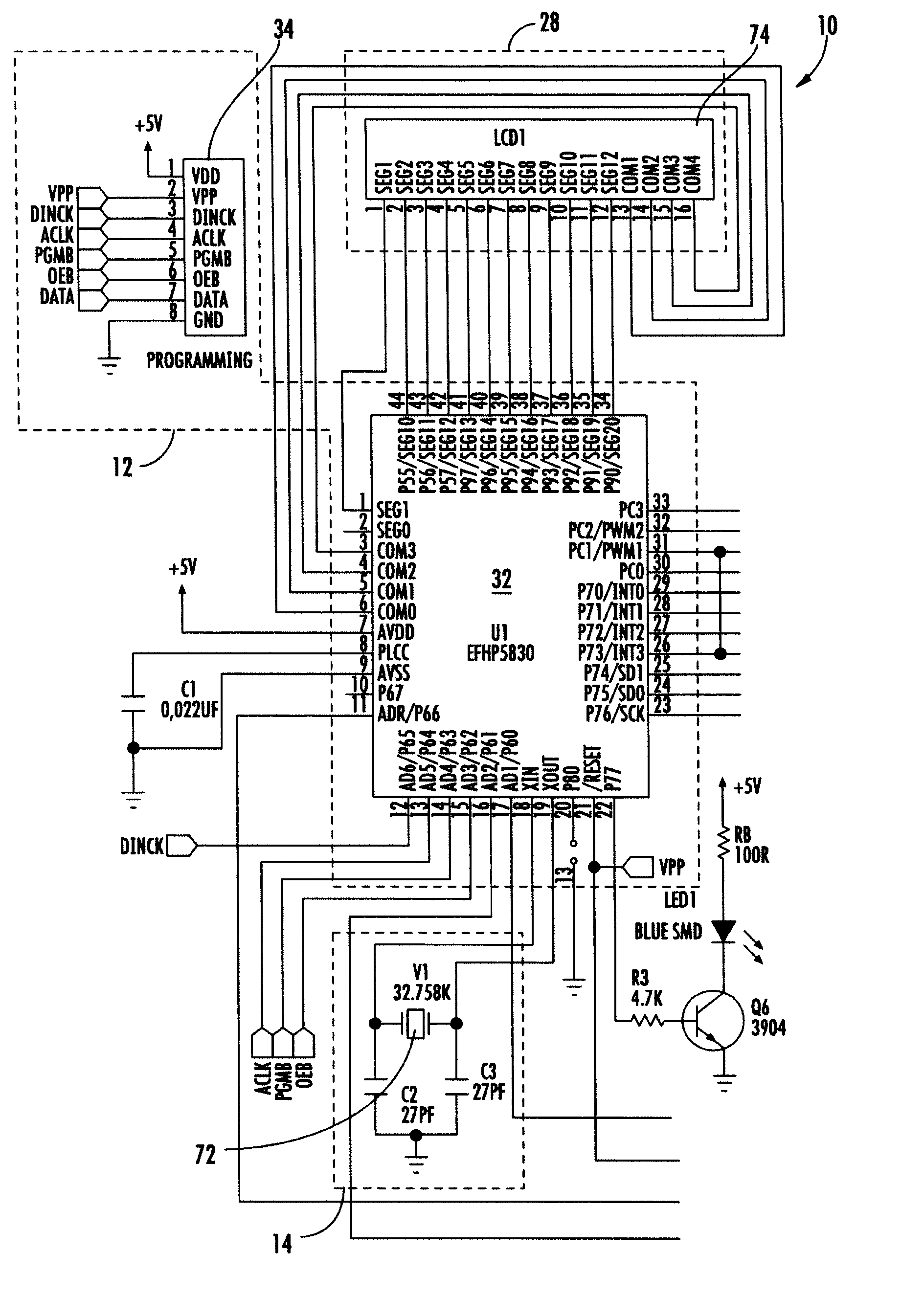
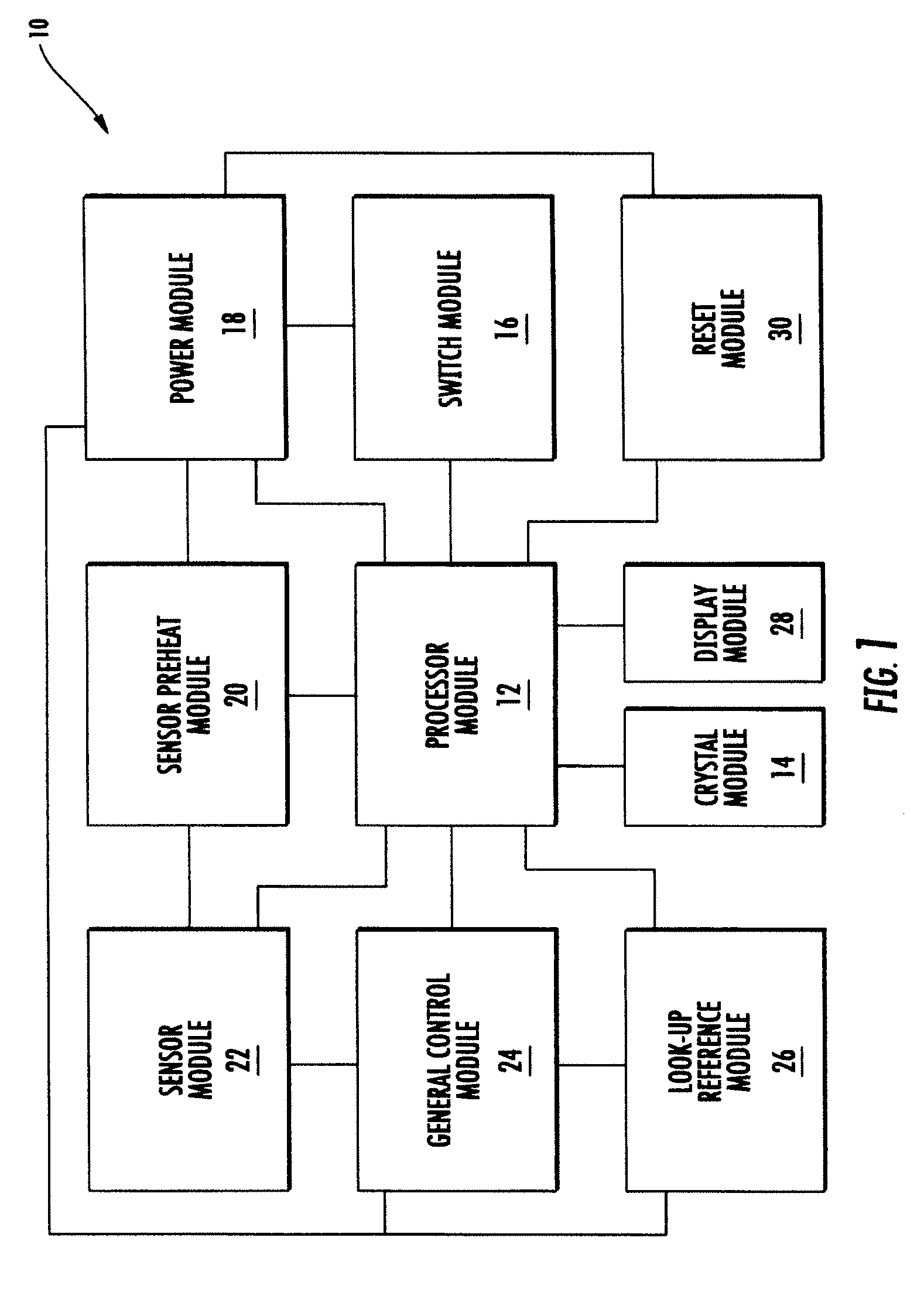
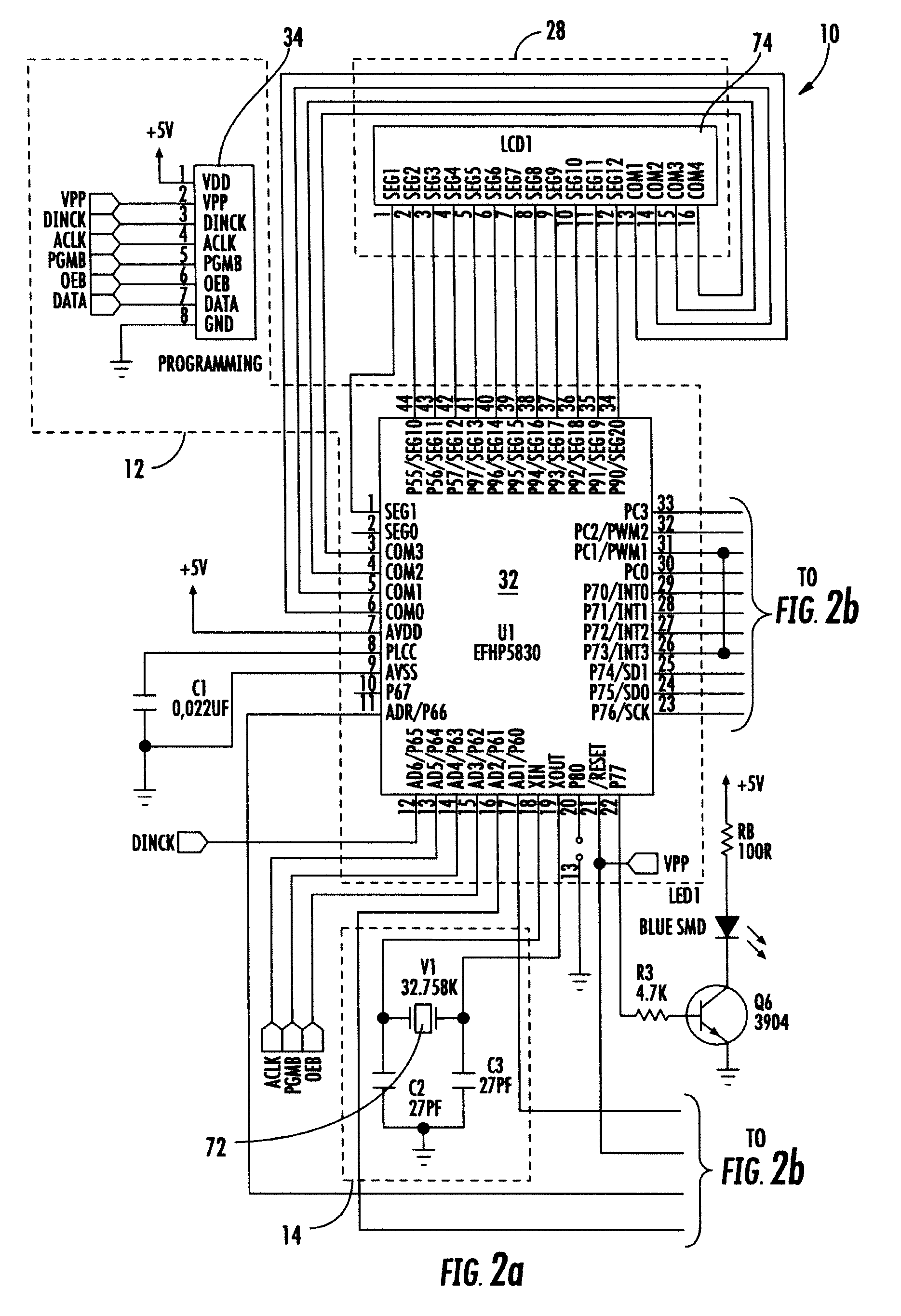
[0026]FIGS. 1 and 2 show a breath tester device 10 in accordance with a first preferred embodiment of the present invention for testing a breath sample from the user of the device and calculating the blood alcohol content of the breath sample. As is seen in the block diagram of FIG. 1 and the circuit schematic of FIGS. 2, the breath tester 10 comprises the following modules: Processor Module 12; Crystal Module 14; Switch Module 16; Power Module 18; Sensor Preheat Module 20; Sensor Module 22; General Control Module 24; Look-Up Reference Module 26; Display Module 28; and Reset Module 30. The individual modules have been organized and named for purposes of convenience in describing the structure and arrangement of components in this preferred embodiment and should not be considered as limiting in any manner.

[0027] As is seen in FIG. 1, the Processor Module 12 is central to and electrically coupled to the remaining modules. In addition, the Power Module 18 is also coupled to the Sensor...


PUM

PropertyMeasurementUnit
resistanceaaaaaaaaaa
voltageaaaaaaaaaa
voltageaaaaaaaaaa

Abstract

The present invention relates to a portable, personal breath tester device for testing the blood alcohol content of the user of the device. The breath tester comprises a circuit board, wherein a sensor, a liquid crystal display, and a processing unit are installed on and electrically connected to the circuit board. The processing unit receives a voltage signal from the sensor representing the blood alcohol content of the user and converts the voltage signal to a precise value that is displayed on the liquid crystal display.

Description

CROSS-REFERENCE TO RELATED APPLICATIONS [0001] This application claims the benefit of U.S. provisional patent application No. 60 / 746,716, filed on May 8, 2006.BACKGROUND OF THE INVENTION [0002] 1. Field of the Invention [0003] The present invention relates the gaseous breath detection devices, and methods for using the same, and more particularly to a portable personal gaseous breath detection device incorporating digital circuitry to analyze a sample of alveolar air from the user of the device for the presence of alcohol. [0004] 2. Background Art [0005] The present invention relates generally to devices and methods for determining the concentration of alcohol in a mixture of gases and more particularly, the invention relates to a device and method for determining the concentration of alcohol in a breath sample for application in sobriety detection systems. [0006] Various techniques have been employed for calculating a person's blood alcohol concentration by measuring breath samples...

Claims


Application Information

Patent Timeline
Patent Type & Authority Applications(United States)
IPC IPC(8): G01N33/497
CPCG01N33/497
Inventor BURKE, PAUL C.WONG, CHI WING
Owner HONOR TONE
Why Eureka
Try Eureka