Anti-chop eyes for a paintball marker

Inactive Publication Date: 2008-04-03
DYE PRECISION
View PDF53 Cites 19 Cited by
  • Summary
  • Abstract
  • Description
  • Claims
  • Application Information

AI Technical Summary

Benefits of technology

[0009]In view of the foregoing, a need exists for an

Problems solved by technology

However, a deformation of the paintball prior to being fired can lead to jamming in the feed port of the paintball marker or only partial insertion of the paintball into the breech.
A partially inserted paintball may result in the chopping of the paintball and fouling of the

Method used


Image

  • Anti-chop eyes for a paintball marker
  • Anti-chop eyes for a paintball marker
  • Anti-chop eyes for a paintball marker

Examples


Embodiment Construction

,” one will understand how the features of the system and methods provide several advantages over conventional paintball markers.

BRIEF DESCRIPTION OF THE DRAWINGS

[0014]These and other features, aspects and advantages of the present invention will now be described in connection with preferred embodiments of the invention, in reference to the accompanying drawings. The illustrated embodiments, however, are merely examples and are not intended to limit the invention. The following are brief descriptions of the drawings.

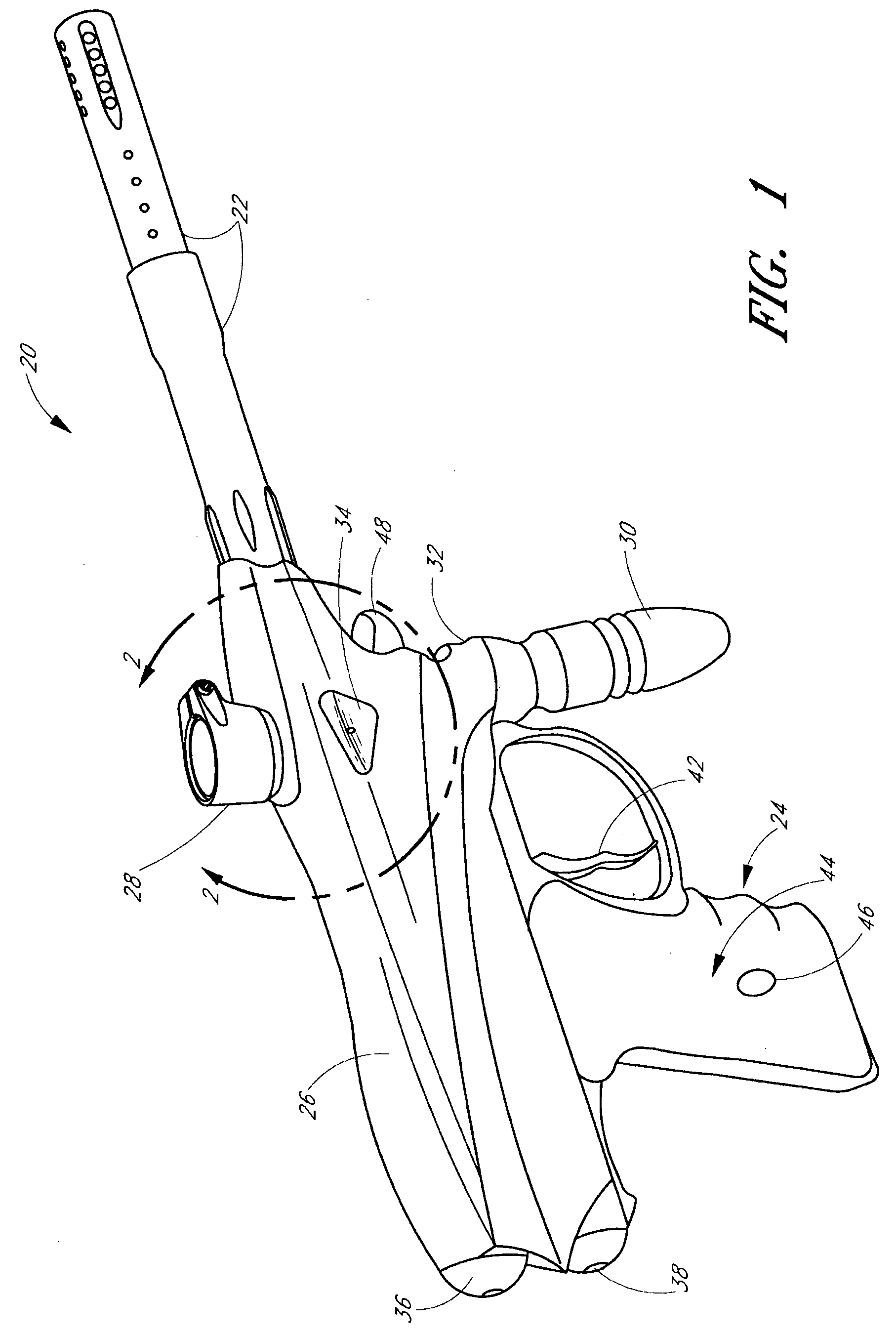
[0015]FIG. 1 depicts a perspective view of a pneumatic paintball marker according to a preferred embodiment of the present invention.

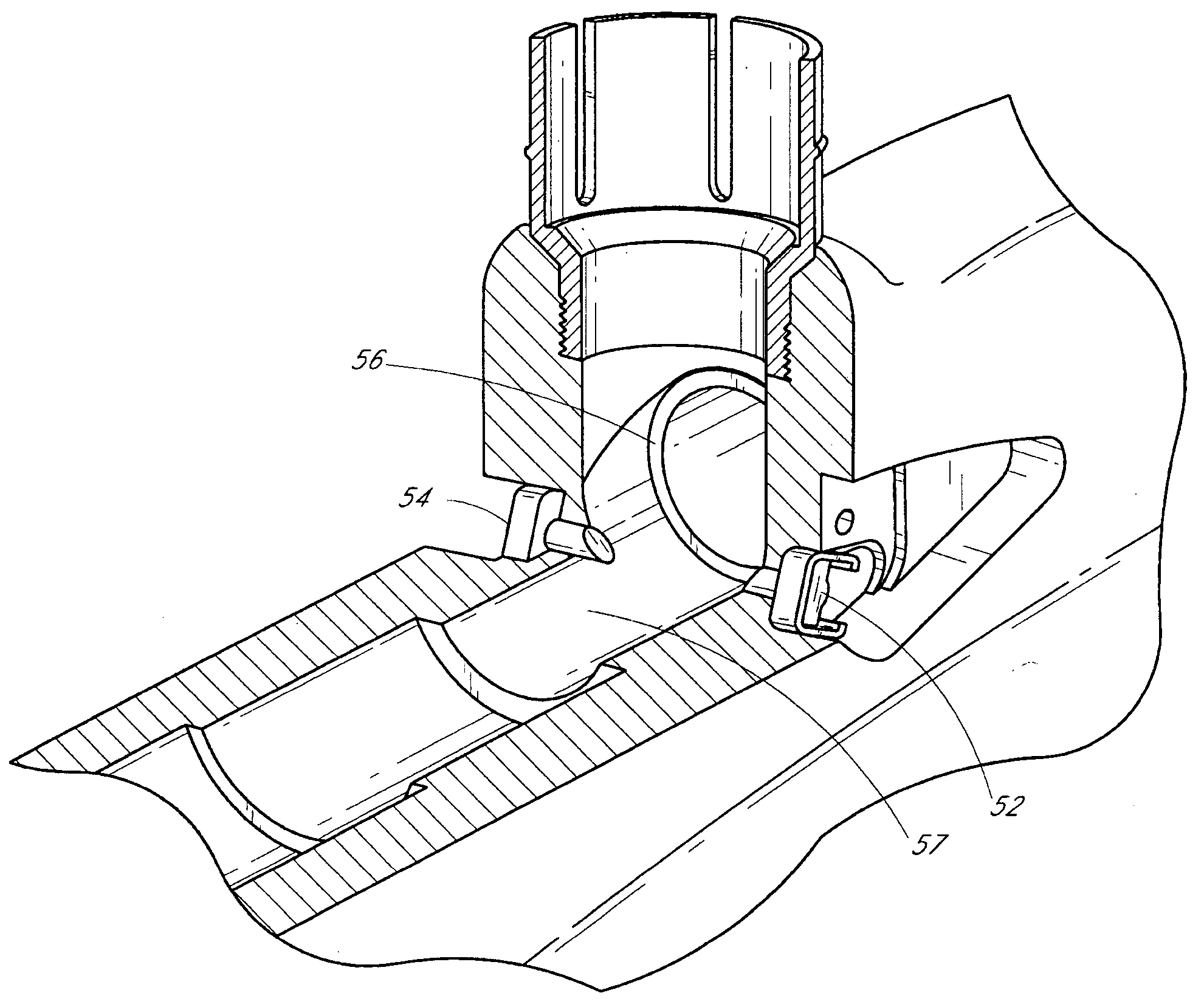
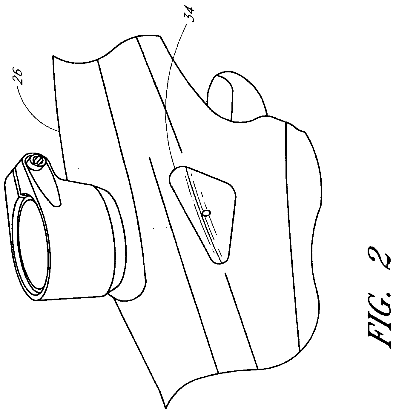
[0016]FIG. 2 depicts a partial perspective view of the pneumatic paintball marker from FIG. 1 with a right cover plate installed over an anti-chop eye system.

[0017]FIG. 3 is an exploded view of exemplary components of the anti-chop eye system from FIG. 2 that are located under the right cover plate.

[0018]FIG. 4 is a cross-section view taken...


PUM


Abstract

An anti-chop system for a pneumatic paintball marker that is automatically cleaned. The anti-chop eye system includes a transmitter and receiver arranged so as to sense the presence of a paintball within a breech using a beam of light. A moving member of the paintball marker automatically wipes at least one surface of the transmitter and/or receiver to remove contaminants such as paint, grease, dirt and the like. By automatically cleaning the anti-chop eye system, the reliability of the system is improved.

Description

BACKGROUND OF THE INVENTION[0001]1. Field of the Invention[0002]The present invention relates to pneumatic guns. More specifically, this invention relates to sensing of a paintball in a paintball marker.[0003]2. Description of the Related Art[0004]Pneumatic paintball markers use a compressed gas, such as air or nitrogen, to propel spherical projectiles called paintballs out of the barrel of the device. Paintballs are typically comprised of a colored liquid enclosed in a fragile gelatin casing. The paintballs are designed to rupture upon impact to mark the target.[0005]In the sport known as “Paintball,” paintballs are fired at an opponent and burst upon contact, so that the colored liquid is deposited on the opponent. However, a deformation of the paintball prior to being fired can lead to jamming in the feed port of the paintball marker or only partial insertion of the paintball into the breech. A partially inserted paintball may result in the chopping of the paintball and fouling o...

Claims


Application Information

Patent Timeline
IPC IPC(8): F41B11/00
CPCF41B11/70F41B11/57F41A21/12F41B11/71
Inventor KAAKKOLA, EEROTHORP, ADAM H.
Owner DYE PRECISION
Why Eureka
Try Eureka