Compressible rotor for a fluid pump

Active Publication Date: 2016-08-16
ECP ENTWICKLUNGSGMBH
View PDF251 Cites 10 Cited by
  • Summary
  • Abstract
  • Description
  • Claims
  • Application Information

AI Technical Summary

Benefits of technology

[0009]The object underlying the invention against the background of the state of the art is to produce a rotor in the simplest possi

Problems solved by technology

As a result, a volume compressibility of the rotor is produced, which leads per se, durin

Method used


Image

  • Compressible rotor for a fluid pump
  • Compressible rotor for a fluid pump
  • Compressible rotor for a fluid pump

Examples


Example

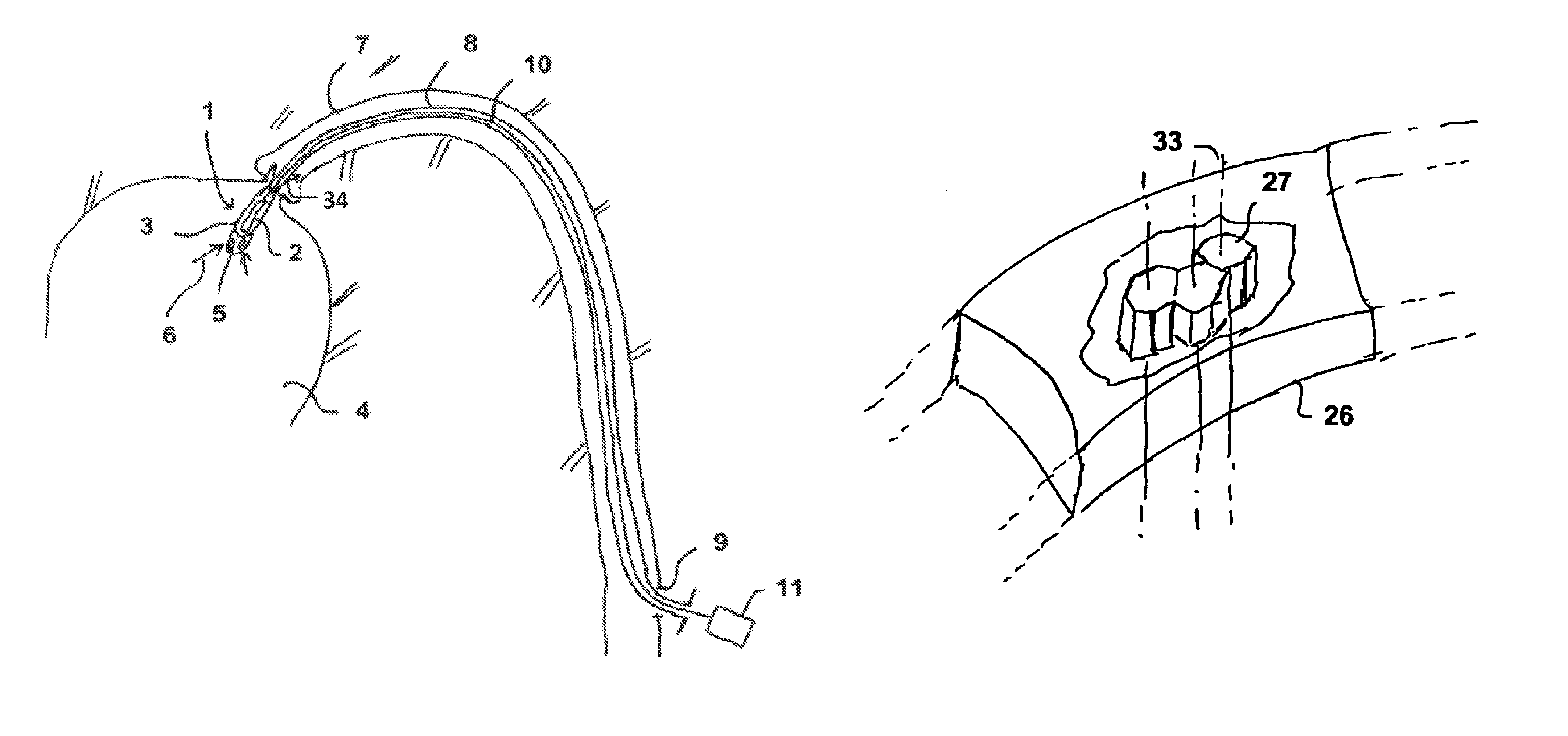
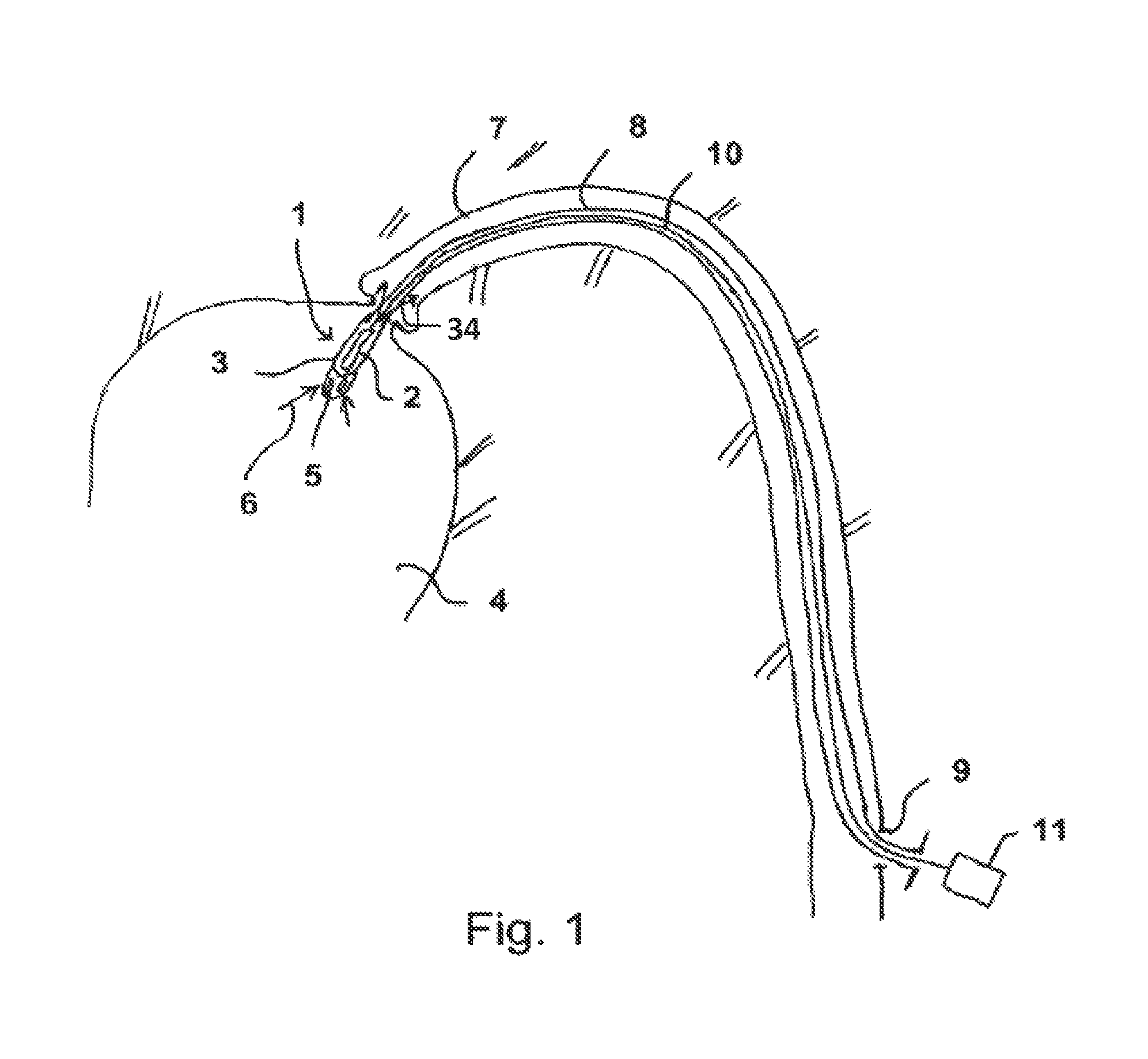
[0059]FIG. 1 shows an axial pump having a rotor 2 and a housing 3 in the interior of a ventricle 4 in schematic view.

[0060]Within the ventricle 4, blood is suctioned in through openings 5 by the pump 1 as indicated by the arrows 6. The blood is expelled again in the direction of the arrows 34 within a blood vessel 7 and hence the pumping function of the heart is replaced or assisted.

[0061]The pump 1 is disposed at the distal end of a hollow catheter 8 which is inserted through the blood vessel 7 into the ventricle 4 and the proximal end thereof protrudes through a lock 9 out of the blood vessel and ultimately out of the body of the patient.

[0062]A drive shaft 10 which can be actuated, with a high speed of rotation, typically above 10,000 revolutions per minute, by means of a motor 11 which is disposed outside the body, is provided within the hollow catheter 8. In the pump 1, the rotor 2 is connected to the shaft 10 and rotates with the latter.

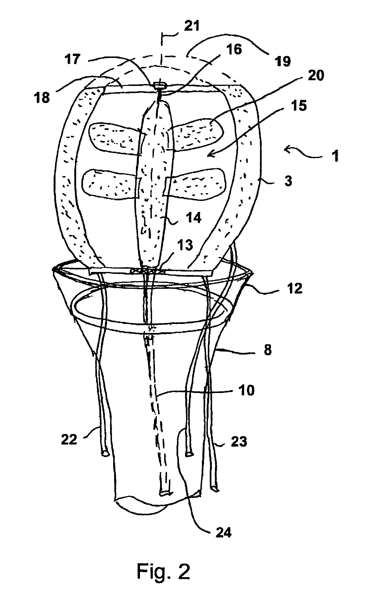
[0063]The pump 1 has a greater diameter ...


PUM

PropertyMeasurementUnit
Fractionaaaaaaaaaa
Volumeaaaaaaaaaa
Pressureaaaaaaaaaa

Abstract

The invention relates to a rotor for a fluid pump, in particular for use in the medical sphere, the rotor being compressible for bringing to the place of use and thereafter being expandable. The compressibility is assisted by the provision of cavities, in particular also production of the rotor at least partially from a foam.

Description

BACKGROUND OF THE INVENTION[0001]The present invention resides in the field of mechanical engineering, in particular precision engineering, and relates to rotors for fluid pumps.[0002]Rotary pumps are common knowledge but these are constantly being improved, in particular for special applications. Thus axial pumps have become known which have a rotor conveying fluid in the axial direction in a housing, rotor and housing being deformable, advantageously compressible, in order to bring these before operation to a desired place of use which is difficult to access and in order to decompress and operate them there.[0003]Such pumps are used for example in medicine in microconstruction form in order to be introduced into the body of a patient, for example via the bloodstream, and to be operated there either in a blood vessel or in a ventricle.[0004]The pumps can be compressed such that they can be pushed through the blood vessel and then possibly decompressed in a larger body cavity in ord...

Claims


Application Information

Patent Timeline
IPC IPC(8): F04D3/00F04D29/18F04D29/24A61M1/10A61M1/12
CPCF04D3/00F04D29/181F04D29/24A61M1/1024A61M1/1034A61M1/122A61M1/125A61M60/414A61M60/148A61M60/806A61M60/825A61M60/808A61M60/237A61M60/13F05B2240/311F05B2280/6012A61M60/135A61M60/818A61M60/205
Inventor SCHUMACHER, JOERGSCHECKEL, MARIOSCHLICHT, HENNING
Owner ECP ENTWICKLUNGSGMBH
Why Eureka
Try Eureka