Gum dispenser for dispensing gum by vertical lifting

Active Publication Date: 2012-05-10
ID PLATECH
View PDF22 Cites 12 Cited by
  • Summary
  • Abstract
  • Description
  • Claims
  • Application Information

AI Technical Summary

Benefits of technology

[0015]The present invention is characterized in that gum can be precisely discharged one by one at a time, and no defects occ

Problems solved by technology

The gum formed in a tablet shape is sealingly stored in a container made from a plastic or the like; however the container has a disadvantage in that it is needed to take out one or more gums with fingers by opening a lid or a container is made upside down, thus taking out a certain number of gums.
In this case, it is almost impossible to precisely take out a desired number of gums because the container is inherently designed to have only a storing function.
In the above constructions, there are disadvantages in that with the gums being filled in the inner container, when two gums are placed on the support stopper 22 secured to the upper side of the up and down movement sha

Method used


Image

  • Gum dispenser for dispensing gum by vertical lifting
  • Gum dispenser for dispensing gum by vertical lifting
  • Gum dispenser for dispensing gum by vertical lifting

Examples


Example

[0024]

10: inner container11: support surface11a: through hole12: up and down movement surface13: up and down movement hole14: reinforcing rib20: outer container21: up and down movement shaft21a: cut-away piece21b: engaging shoulder part22: support stopper30: lid31: discharge hole32: cut-away cover32a: cutting line33: connection part34: pulling partcut-away groove36: inclined wings

BEST MODES FOR CARRYING OUT THE INVENTION

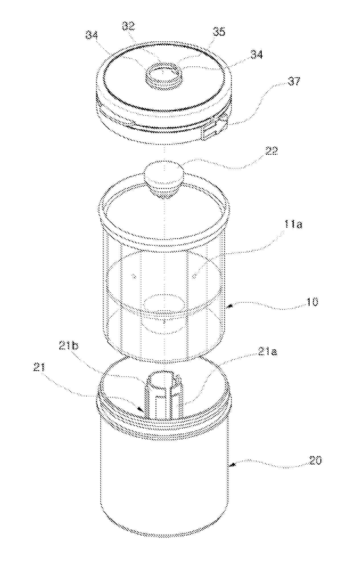
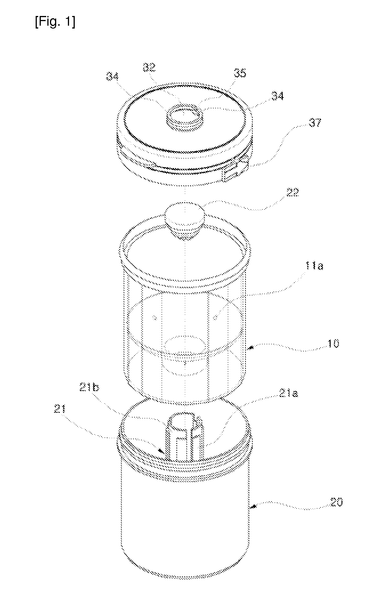
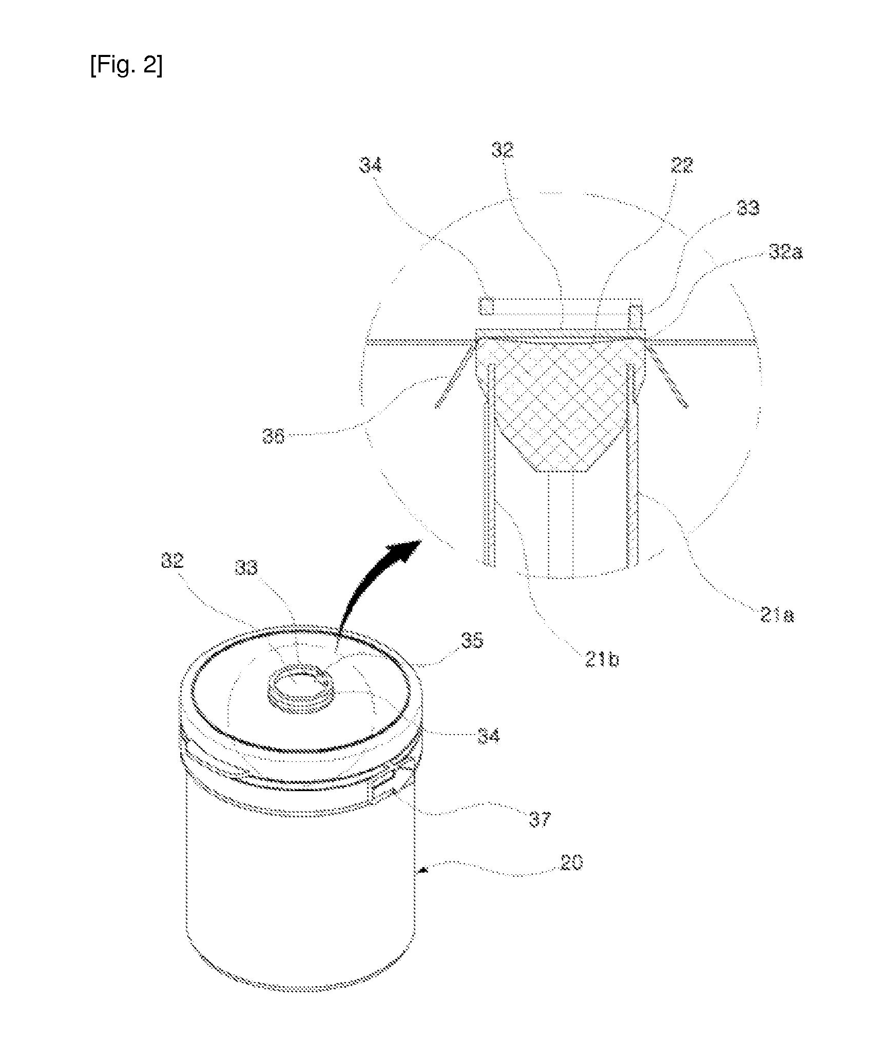
[0025]In the present invention, a gum dispenser for dispending gum by vertical lifting comprises an inner container 10 moving up and down as it is inserted in an up and down movement shaft 21 of an outer container 20; and a support stopper 22 being engaged to an upper side of the up and down movement shaft 21, with the gum being placed at its upper side one by one at a time, and the placed gum is discharged through a discharge hole 31 formed at a lid 30 tightly secured to the inner container 10, wherein the up and down movement shaft 21 is injection-molded integrally...


PUM


Abstract

The present invention relates to a gum dispenser for automatically dispensing gum by the vertical lifting of a gum case. Particularly, the present invention provides a container that has a self-sealing means, accurately dispenses a piece of gum one by one, prevents the generation of container defects, and provides ease of operation and molding. Currently, in the above operation structure, an inner case receiving gum therein is fitted in a lifting shaft of an outer case to be lifted or lowered so that a piece of gum is pushed up to an upper end of the lifting shaft, and then the gum is exposed to a dispensing hole perforated in a lid, which is coupled with the inner case, one by one for a user to enjoy. The above structure, however, has a disadvantage in that if two pieces of gum are lifted to the upper end of the lifting shaft and the lifting shaft is exposed to the perforated hole of the lid, then the lifting shaft and the dispensing hole correspond to each other 1:1 so that the two pieces of gum pop out, which makes the gum difficult to catch. In addition, if the lifting shaft is molded integrally with the outer case, the lifting shaft is likely to be twisted or bent due to the thickness thereof in the cooling procedure during the molding thereof so that it is difficult to achieve a precisely standing structure. Furthermore, if the inner case is repetitively lifted or lowered in the outer case, an outer force may be applied in the lifting motion according to a vacuum state, so that smooth operation becomes impossible and longer molding time is required in the molding. In addition, in the state that the lid is sealingly coupled with the outer case and the inner case for the sealing of the container during storage or delivery thereof, a perforated lid for implementing the dispensing hole may be pressed by the lifting shaft and the container may burst. If the perforated lid is formed to be thick in order to prevent the bursting, a pulling portion to be pulled for cutting the perforated lid is likely to be cut, and implementation of the dispensing hole may fail. As a result, the present invention is aimed at resolving the above problems.

Description

TECHNICAL FIELD[0001]The present invention relates to a gum dispenser for dispensing gum with an up and down movement of a gum container which is characterized in that a container per se has a sealing part and makes it possible to precisely discharge a piece of gum at a time without having any defects in a container during an actual use or distribution and has easier operation and formation.BACKGROUND ART[0002]The gum formed in a tablet shape is sealingly stored in a container made from a plastic or the like; however the container has a disadvantage in that it is needed to take out one or more gums with fingers by opening a lid or a container is made upside down, thus taking out a certain number of gums. In this case, it is almost impossible to precisely take out a desired number of gums because the container is inherently designed to have only a storing function.[0003]The Korean utility model registration number 424929 filed by the same applicant as the present invention is directe...

Claims


Application Information

Patent Timeline
IPC IPC(8): B65D83/04
CPCB65D83/0005B65D83/0409B65D85/60B65D2583/044B65D83/00B65D83/04
Inventor KIM, KANG CHEAL
Owner ID PLATECH
Why Eureka
Try Eureka