Fuel cell system

Active Publication Date: 2011-06-30
HONDA MOTOR CO LTD
View PDF5 Cites 14 Cited by
  • Summary
  • Abstract
  • Description
  • Claims
  • Application Information

AI Technical Summary

Benefits of technology

[0018]In the present invention, the space in the casing is divided into the module section where the fuel cell module is provided, the fluid supply section where the oxygen-containing gas supply apparatus is provided, and the electrical equipment section where the power converter and the control device are provided. In the structure, the space in the casing is divided depending on the operating temperatures and functions, thereby to minimize diffusion of heat and fluid. In terms of functionality, the optimum layout is achieved advantageously.
[0019]Further, the fluid supply section forms part of an outer wall of the casing. Accordingly, the fluid supply section is cooled efficiently, and does not become hot easily. Likewise, the electrical equipment section forms part of the outer wall of the casing. Accordingly, the electrical equipment section is cooled efficiently, and does not become hot easily. Thus, heat influence on the devices that should be used at low temperature, such as the fluid supply section containing pumps and the electrical equipment section containing the control device is prevented as much as possible. The desired functions of devices are maintained, and the devices are operated reliably.
[0020]Further, the inner partition is provided in the casing in order to form the detour channel for preventing the oxygen-containing gas from flowing straight from the first air inta

Problems solved by technology

Therefore, in particular, in the case where a high temperature fuel cell is used, the optimum layout of the devices in the fuel cell system cannot be achieved depending on the operating temperature ranges and functions.
Further, heat management and fluid management such as heat insulation and prevention of fluid diffusion or the like are not performed sufficiently.
Therefore, in particular, in the case where the high

Method used


Image

  • Fuel cell system
  • Fuel cell system
  • Fuel cell system

Examples


first embodiment

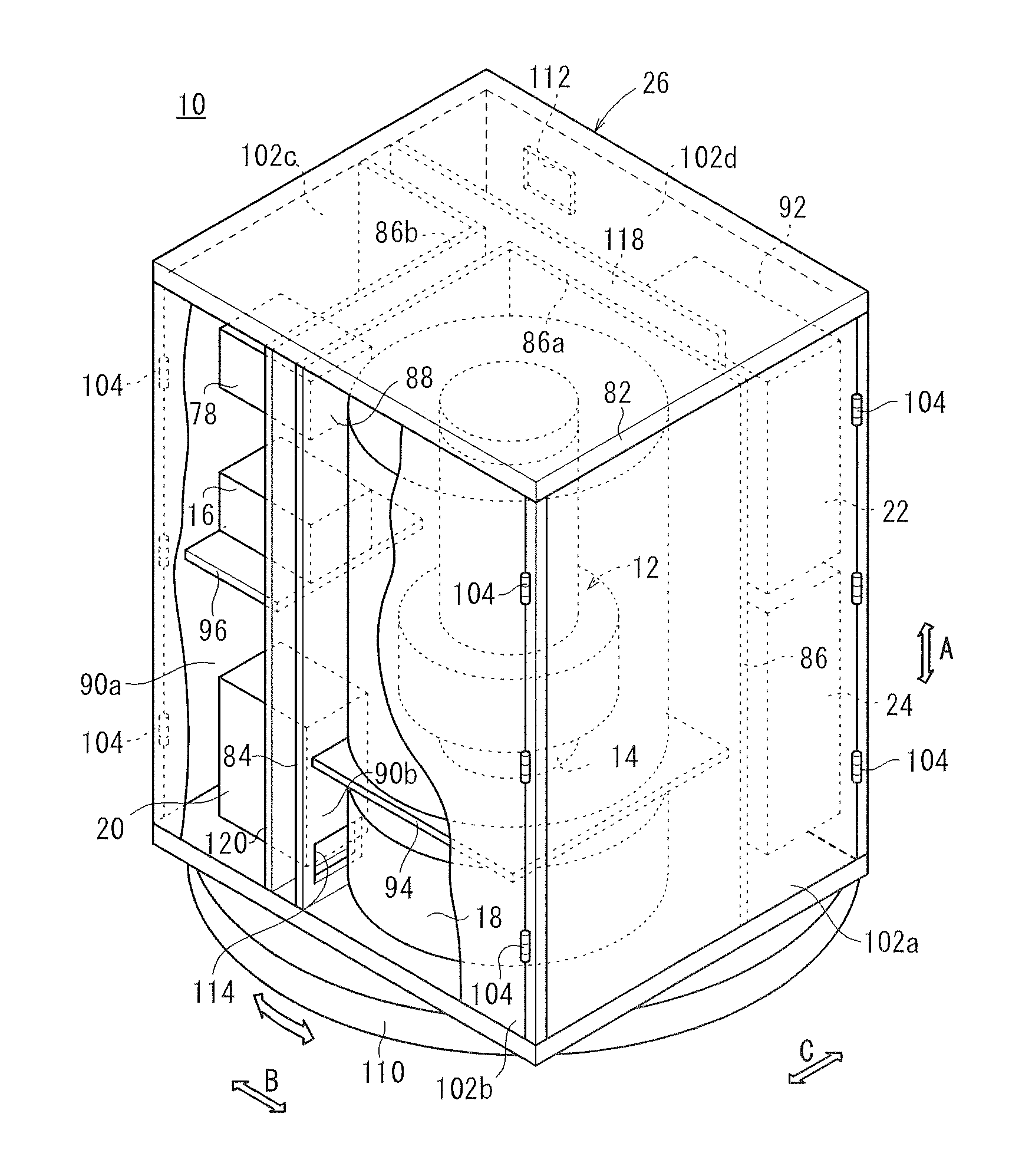
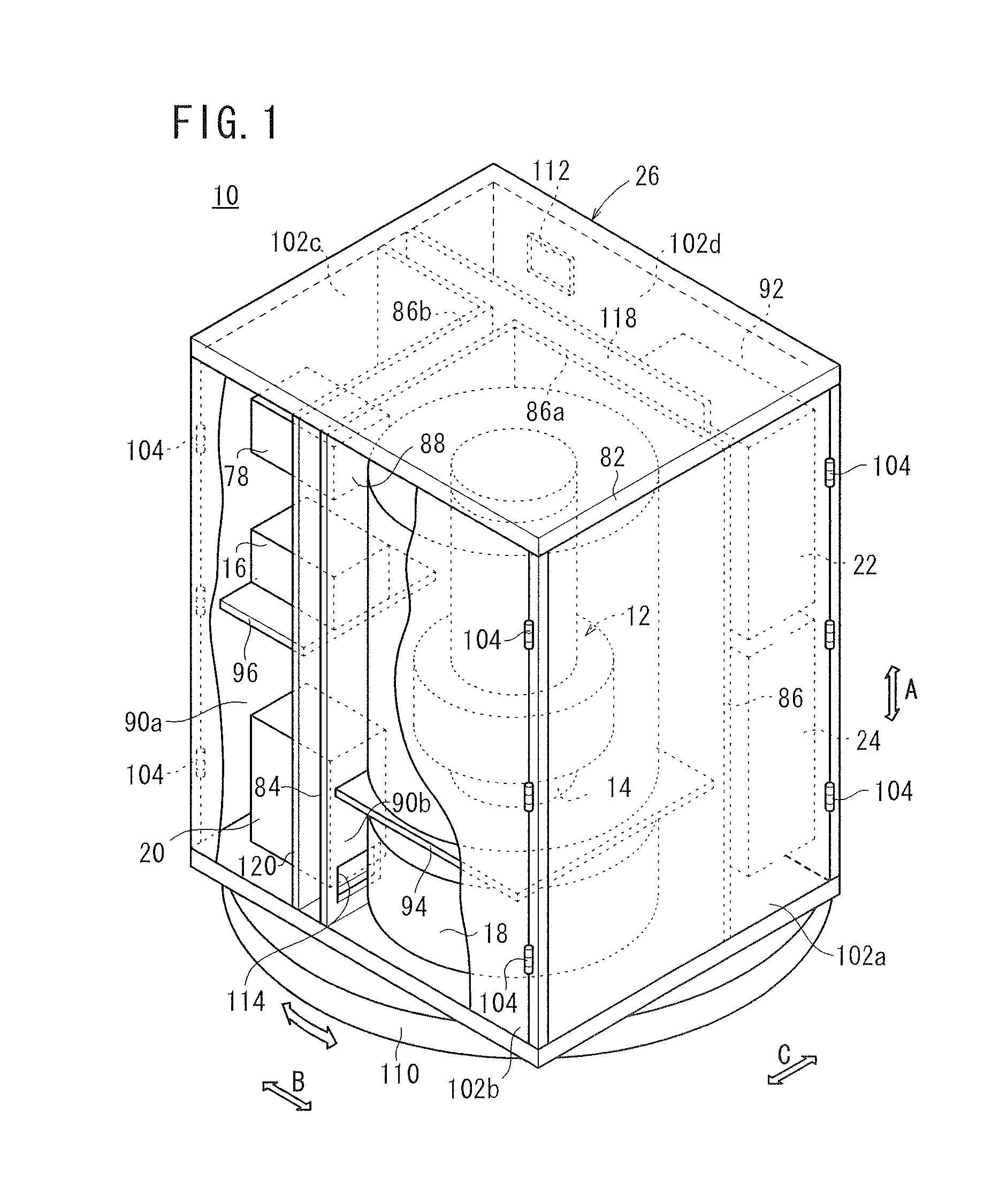
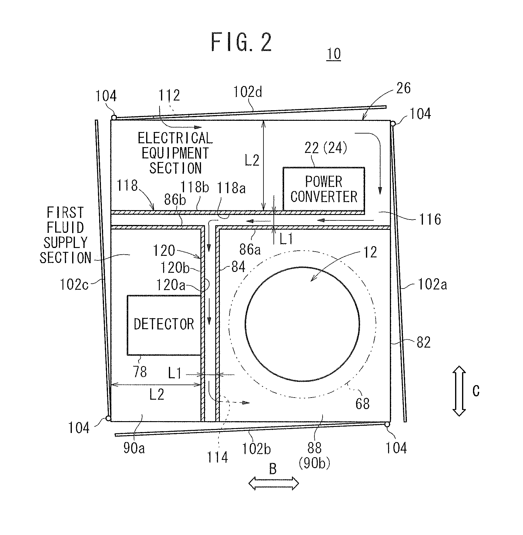
[0045]As shown in FIGS. 1 to 3, a fuel cell system 10 according to the present invention is used in various applications, including stationary and mobile applications. For example, the fuel cell system 10 is mounted on a vehicle. The fuel cell system 10 includes a fuel cell module 12 for generating electrical energy in power generation by electrochemical reactions of a fuel gas (hydrogen gas) and an oxygen-containing gas (air), a combustor 14 for raising the temperature of the fuel cell module 12, a fuel gas supply apparatus (including a fuel gas pump) 16 for supplying the fuel gas to the fuel cell module 12, an oxygen-containing gas supply apparatus (including an air pump) 18 for supplying an oxygen-containing gas to the fuel cell module 12, a water supply apparatus (including a water pump) 20 for supplying water to the fuel cell module 12, a power converter 22 for converting the direct current electrical energy generated in the fuel cell module 12 to electrical energy according to...

second embodiment

[0095]FIG. 6 is a perspective view schematically showing a fuel cell system 130 according to the present invention. FIG. 7 is a plan view showing a fuel cell system 130. FIG. 8 is a front view showing the fuel cell system 130.

[0096]The constituent elements that are identical to those of the fuel cell system 10 according to the first embodiment are labeled with the same reference numerals, and descriptions thereof will be omitted. Further, also in third to sixth embodiments as described later, the constituent elements that are identical to those of the fuel cell system 10 according to the first embodiment are labeled with the same reference numerals, and descriptions thereof will be omitted.

[0097]A fluid supply section 90 is provided between a first vertical partition plate 84 and an outer frame 82 of a casing 132 of the fuel cell system 130. The fluid supply section 90 is vertically divided into two sections, i.e., a first supply section 136 and a second supply section 138 by a late...

third embodiment

[0101]FIG. 9 is a perspective view schematically showing a fuel cell system 150 according to the present invention. FIG. 10 is a plan view showing the fuel cell system 150, and FIG. 11 is a front view showing the fuel cell system 150.

[0102]The space in a casing 152 of the fuel cell system 150 is divided in a direction indicated by an arrow B by a first vertical partition plate 84 and a second vertical partition plate 86 arranged at a predetermined interval in the direction indicated by the arrow B.

[0103]The space in the casing 152 is divided in the direction indicated by the arrow B, into the module section 88, the fluid supply section 90, and the electrical equipment section 92. The fluid supply section 90 is interposed between the module section 88 and the electrical equipment section 92. The fluid supply section 90 has the same structure as in the case of the second embodiment, and the description thereof will be omitted.

[0104]An inner partition 154 having a substantially L-shape...


PUM


Abstract

A case configuring a fuel cell system is divided into a module section, a first fluid supply section, a second fluid supply section, and an electric section. The electric section is provided with a first intake vent for intake of an oxidant gas from outside the case into the electric section. The second fluid supply section is provided with a second intake vent for intake of the oxidant gas subjected to intake from the first intake vent, into an oxidant gas supply device. The case is internally provided with first and second internal partitions which generate a bypass path for blocking straight flow of the oxidant gas from the first intake vent to the second intake vent.

Description

TECHNICAL FIELD [0001]The present invention relates to a fuel cell system including a fuel cell module, an oxygen-containing gas supply apparatus, a power converter, a control device, and a casing at least containing the fuel cell module, the oxygen-containing gas supply apparatus, the power converter, and the control device.BACKGROUND ART [0002]Typically, a solid oxide fuel cell (SOFC) employs a solid electrolyte of ion-conductive oxide such as stabilized zirconia. The solid electrolyte is interposed between an anode and a cathode to form an electrolyte electrode assembly. The electrolyte electrode assembly is interposed between separators (bipolar plates). In use, normally, predetermined numbers of the electrolyte electrode assemblies and the separators are stacked together to form a fuel cell stack.[0003]As the fuel gas supplied to the fuel cell, normally, a hydrogen gas produced from hydrocarbon raw material by a reformer is used. In general, in the reformer, a reformed raw mate...

Claims


Application Information

Patent Timeline
IPC IPC(8): H01M8/04
CPCH01M8/04014H01M8/0494H01M8/0618H01M8/0662H01M8/083H01M8/086Y02E60/526H01M2008/1095H01M2008/1293H01M2008/147Y02E60/50Y02E60/525H01M8/2475
Inventor SAITO, BUNICHIMIYAZAKI, TOMIOFUJISAWA, KIMIKO
Owner HONDA MOTOR CO LTD
Why Eureka
Try Eureka