Electronic equipment housing

a technology for electronic equipment and equipment housings, applied in the direction of cooling/ventilation/heating modifications, rigid containers, apparel, etc., can solve the problems of electronics equipment becoming operationally unreliable, generating a substantial amount of heat, and affecting the operation of the equipmen

Inactive Publication Date: 2011-09-08
RAMODIEN SHANE
View PDF18 Cites 16 Cited by
  • Summary
  • Abstract
  • Description
  • Claims
  • Application Information

AI Technical Summary

Benefits of technology

[0020]In a preferred embodiment, electronic equipment is arranged in the equipment unit and the duct arrangement has inlets positioned directly proximate to outlets for air exhausted from the electronic equipment so that diffusion of air exhausted from the electronic equipment throughout the equipment unit is minimised

Problems solved by technology

The electronic equipment housed in these equipment units can generate a substantial amount of heat.
Heat does dissipate to some extent within the equipment unit, and dissipate into the room in which the equipment unit sits, but this process is less than ideal.
If the equipment is operating beyond its recommended temperature range, the electronics equipment can become operationally unreliable, system performance may be compromised, or system failure may result.
The amount of heat generated within the equipment room increases substantially, and the effective operating temperature can be too high, and difficult to control.
Conditions can be uncomfortable for staff when working in the equipment room.
This inevitably involves changing or supplementing the building's HVAC infrastructure and, consequently, is very likely to require approval, especially if the premises are leased rather than owned.
Also, it may not be physically possible to deliver the required cooling to the equipment room due to infrastructure constraints.
Various configurations of fan units or air conditioning units are available that are intended to be housed within an equipment unit, but existing solutions do not adequately address the challenges of safe and reliable operation of equipment within the equipment unit.
As an example, inadequate control of condensation created by operation of a built-in air conditioner can compromise equipment operation.

Method used


Image

  • Electronic equipment housing
  • Electronic equipment housing
  • Electronic equipment housing

Examples


Embodiment Construction

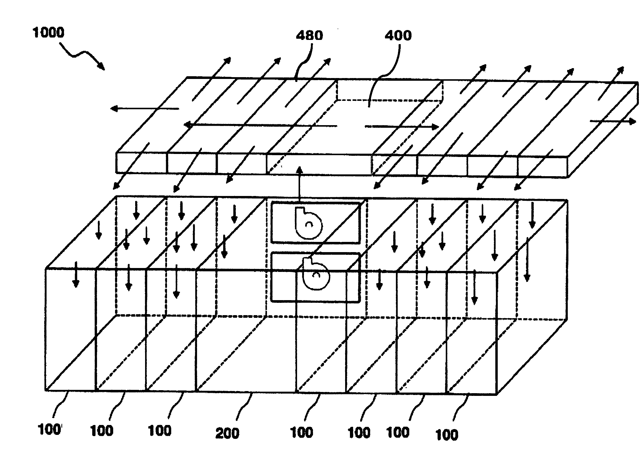
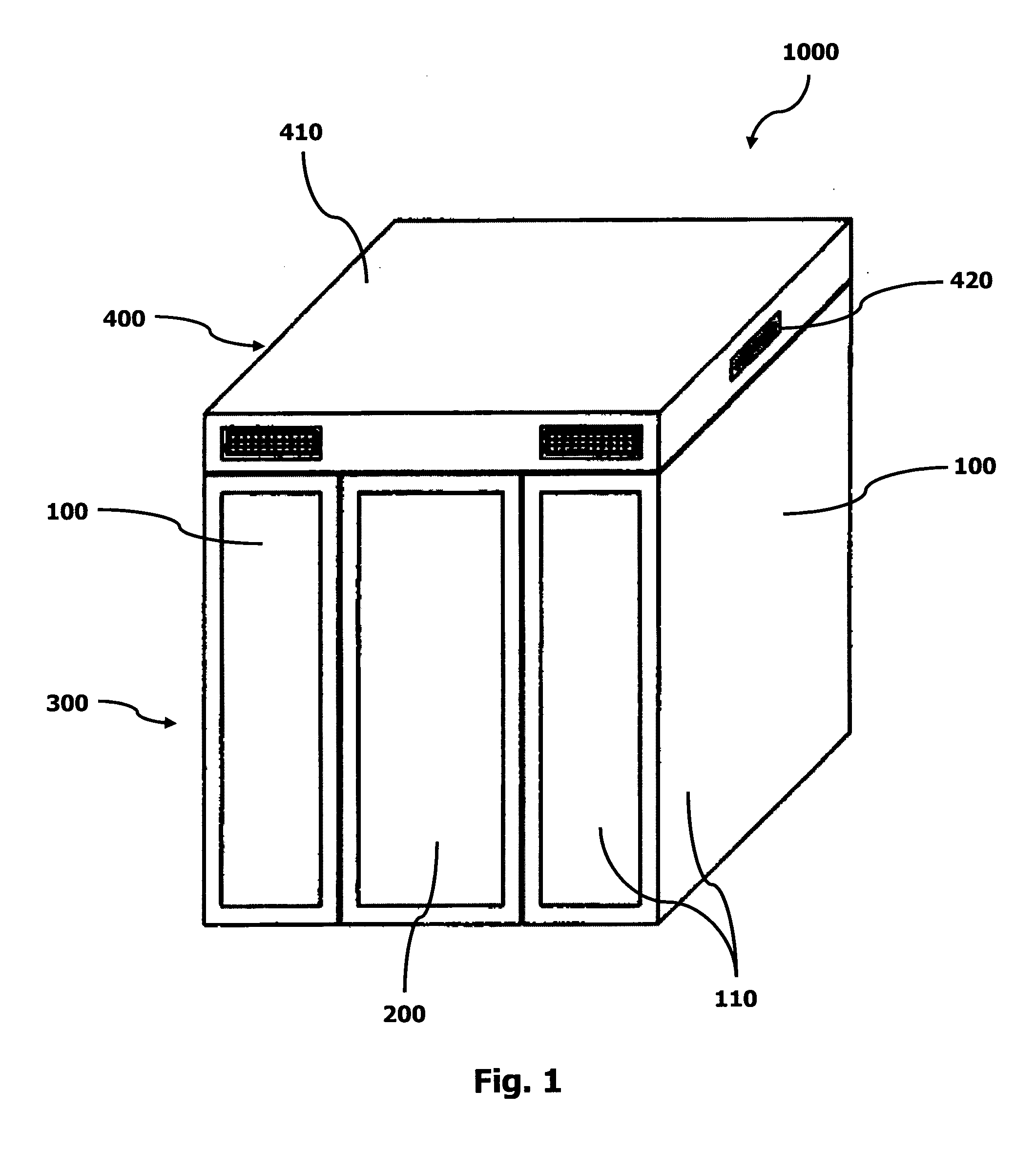
[0032]FIG. 1 depicts an electronic equipment housing 1000 having a lower housing base 300 comprising two equipment units 100 and a conditioning unit 200. An upper housing plenum 400 having an upper surface 410 is mounted on top of the lower housing base 300, so as to cover and engage the equipment units 100 and the conditioning unit 200.

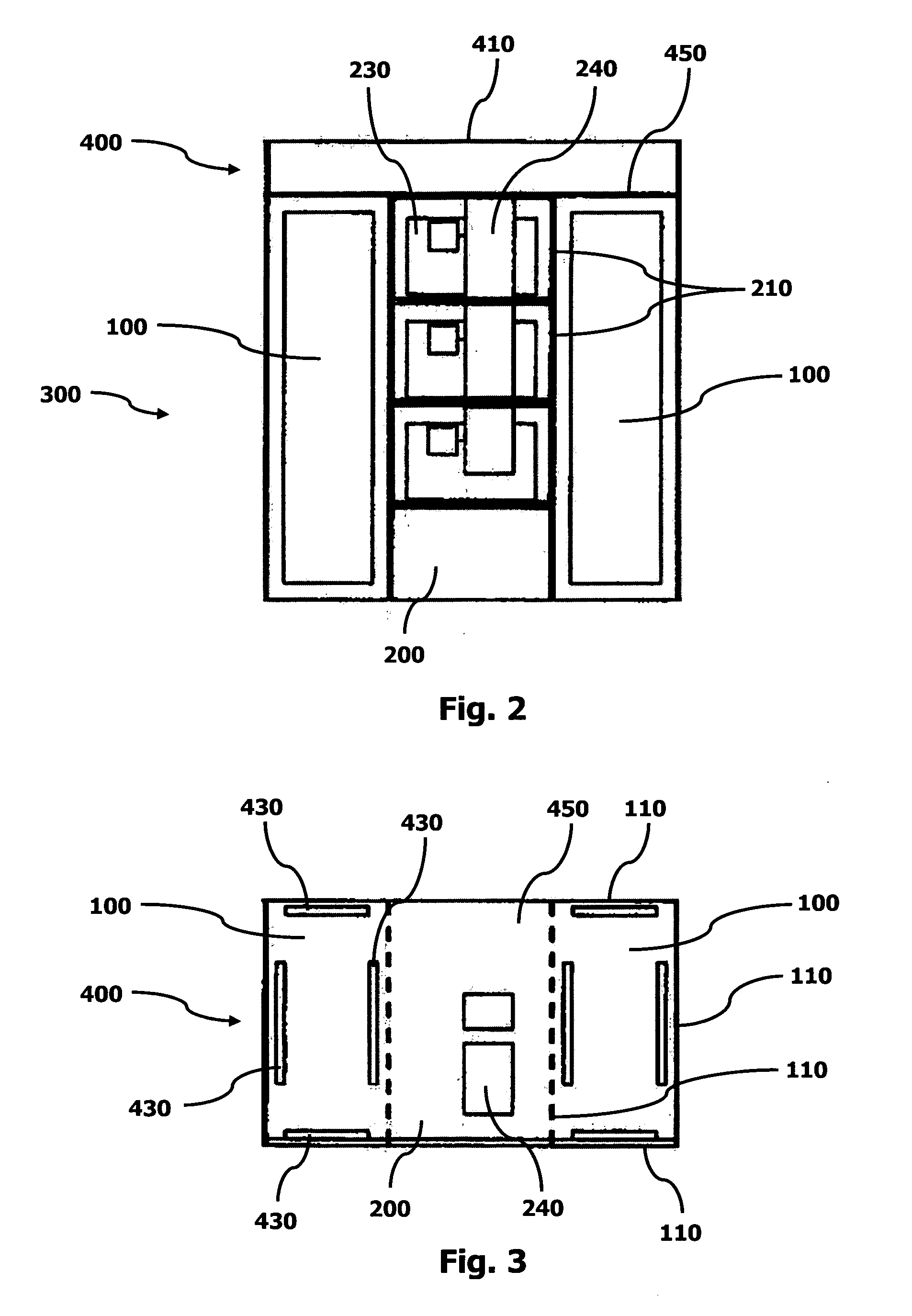
[0033]The equipment units 100 are generally rectangular prisms with four peripheral walls 110. The equipment units 100 and the conditioning unit 200 are formed with the same height and depth dimensions, such that the equipment and conditioning units 100, 200 can be arranged flush with one another side-by-side. Vents 420 are provided on side walls of the housing plenum 400 and are selectively operable to allow air to be vented from the housing plenum 400.

[0034]As shown in FIGS. 2 and 4, the conditioning unit 200 houses air conditioners 210, having fans 220, cooling elements 230 and supply ducts 240, for supplying conditioned air to the housing plenum ...


PUM


Abstract

An electronic equipment housing (1000) comprises a housing body (300) comprising a conditioning unit (200) housing an air conditioner (210) and an equipment unit (100) adapted to house electrical equipment. A housing plenum (400) is mounted on top of the lower housing body (300), so as to cover and engage the equipment unit (100). The housing plenum (400) has at least one aperture (430) formed in the lower surface (450), wherein the aperture (430) is adapted to allow air to pass from the housing plenum (400) directly into the equipment unit (100) and wherein the housing plenum (400) is in fluid communication with the air conditioner (210). A duct arrangement (500) provides fluid communication between the equipment unit (100) and the air conditioner (210), wherein the duct arrangement (500) is adapted to return air from the equipment unit (100) to the air conditioner (210).

Description

FIELD OF THE INVENTION[0001]The present invention relates to electronic equipment housing for controlling the environment for electronic equipment such as switchgear or computer servers.BACKGROUND[0002]There are various types and sizes of equipment units used for housing electronics equipment, such as switchgear and computer servers. As an example, a standard 42U server rack cabinet has a height of 2025 mm, width 600 mm and depth of 1050 mm. The electronic equipment housed in these equipment units can generate a substantial amount of heat. Heat does dissipate to some extent within the equipment unit, and dissipate into the room in which the equipment unit sits, but this process is less than ideal. If the equipment is operating beyond its recommended temperature range, the electronics equipment can become operationally unreliable, system performance may be compromised, or system failure may result.[0003]Furthermore, in many corporate IT departments and data centres, a room will be al...

Claims


Application Information

Patent Timeline
Patent Type & Authority Applications(United States)
IPC IPC(8): H05K7/20B65D85/00
CPCH05K7/20736
Inventor RAMODIEN, SHANE
Owner RAMODIEN SHANE
Why Eureka
Try Eureka