
Damper device

Inactive Publication Date: 2008-04-03
NIDEC SANKYO CORP
View PDF9 Cites 2 Cited by
  • Summary
  • Abstract
  • Description
  • Claims
  • Application Information

AI Technical Summary

Benefits of technology

[0005]An embodiment of the present invention may advantageously provide a damper device which is capable of reducing a dimension in a turning axial direction of a baffle.
[0007]In accordance with an embodiment of the present invention, the baffle is turned by advancing and retreating operation of the output member and thus the drive unit is not required to be disposed on the turning center axial line of the baffle and dimension in the baffle turning axial direction can be reduced. In addition, the engagement part is located apart from the first moving extended axis which is formed by movement of the output member at a position where the output member penetrates through the output hole part. Therefore, the position of the engagement part is not required to be restricted by the position of the output hole part and thus degree of freedom on design can be improved.
[0010]In accordance with an embodiment of the present invention, the turning axial line of the baffle is located on or in a vicinity of the first moving extended axis of the output member. According to the structure as described above, the engagement part can be disposed at a position apart from the first moving extended axis of the output member and thus the engagement part is located at a position apart from the turning axial line of the baffle to turnably drive the baffle. In addition, a space on the output member side of the baffle is not required to be divided by the output member and thus it is easy to use the space effectively.
[0013]In accordance with an embodiment of the present invention, at least a part of the output member is structured to be adjacent to an inner wall of the case. When the output member is disposed to be adjacent to the inner wall of the case, rigidity of the linear guide part which is formed in the wall face of the case in the vicinity of the output member can be easily enhanced.
[0014]In accordance with an embodiment of the present invention, a width of the drive unit is set to be within a width of the frame in a direction where the second moving extended axis of the engagement part is apart from the first moving extended axis of the output member. According to the structure as described above, the drive unit is not protruded from the frame in the direction where the second moving extended axis of the engagement part is apart from the first moving extended axis of the output member and thus a size of the device can be reduced.

Problems solved by technology

However, when the drive unit is connected to the turnable support part for the baffle, the drive unit is disposed on the turning center axial line of the baffle and thus dimension in a baffle turning axial direction of the damper device becomes large.

Method used


Image

  • Damper device
  • Damper device
  • Damper device

Examples


Embodiment Construction

[0025]An embodiment of the present invention will be described below with reference to the accompanying drawings.

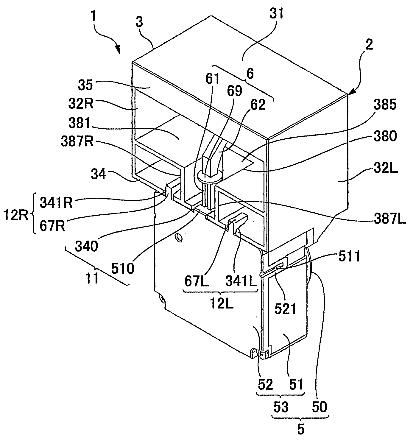
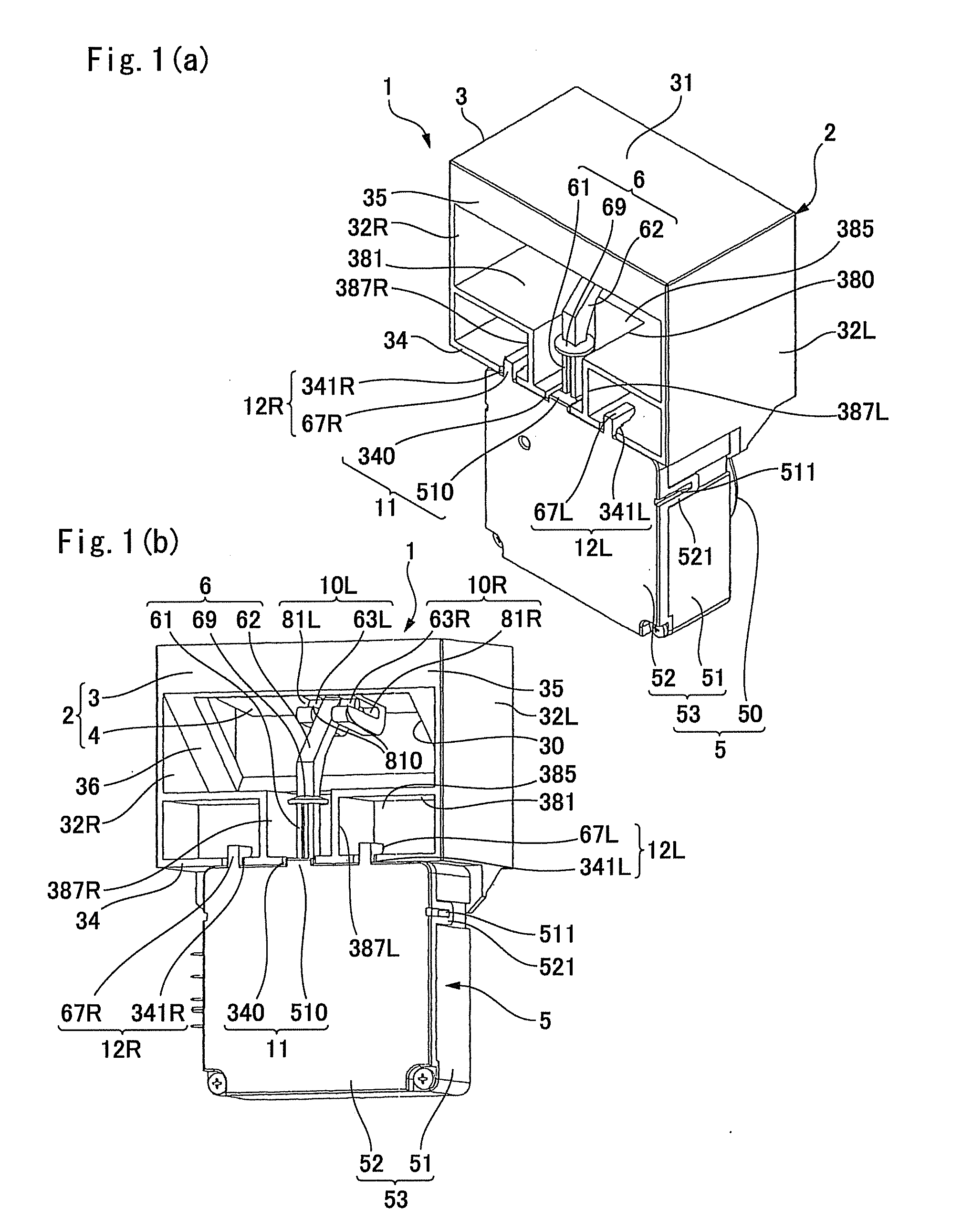
[0026]FIG. 1(a) is a perspective view showing a rear face side of a damper device in accordance with an embodiment of the present invention which is viewed from obliquely above, and FIG. 1(b) is its perspective view which is viewed from obliquely below. FIG. 2 is a longitudinal sectional view showing the damper device shown in FIGS. 1(a) and 1(b). FIG. 3 is an explanatory view showing a baffle unit of the damper device shown in FIGS. 1(a) and 1(b) which is disassembled into a frame and a baffle. In FIG. 3, a buffer member is detached from the baffle.

[0027]A damper device 1 shown in FIG. 1(a) through FIG. 2 is a device for controlling supply of cold air to a storage chamber in a refrigerator. The damper device 1 is generally structured of a baffle unit 2 which is provided with a baffle 4 within a frame 3 and a drive unit 5 which is connected to an under face of the baffle ...


PUM


Abstract

A damper device may include a frame provided with an opening part, a baffle turnably supported on the frame, and a drive unit for turnably driving the baffle to open and close the opening part. The drive unit may include an output member whose tip end side is provided with an engagement part with the baffle and which is linearly advanced and retreated to and from the baffle to turnably drive the baffle. Further, the damper device includes a wall part provided between the driving part and the baffle and formed with an output hole part through which the output member is penetrated. The engagement part is located apart from a first moving extended axis which is formed by movement of the output member penetrating through the output hole part.

Description

CROSS REFERENCE TO RELATED APPLICATION[0001]The present invention claims priority under 35 U.S.C. §119 to Japanese Application No. 2006-272127 filed Oct. 3, 2006, which is incorporated herein by reference.FIELD OF THE INVENTION[0002]An embodiment of the present invention may relate to a damper device which is provided with a baffle for opening or closing a passage for fluid.BACKGROUND OF THE INVENTION[0003]A damper device has been used in a refrigerator or in an air-conditioner for opening / closing a passage for fluid. The damper device includes a frame, a baffle which is turnably supported on the frame, and a drive unit for turnably driving the baffle. The passage through which fluid is passed is opened and closed by the baffle which is turned. Therefore, the above-mentioned damper device is often structured that the drive unit is connected with a turning shaft of the baffle to turnably drive the baffle (see, for example, Japanese Utility Model Laid-Open No. Sho 64-048571).[0004]How...

Claims


Application Information

Patent Timeline
IPC IPC(8): F15D1/00
CPCF24F13/1426F25D17/045F24F2013/1473F24F2013/1446Y10T137/6851
Inventor AKABANE, TOKUYUKI
Owner NIDEC SANKYO CORP
Features
  • Generate Ideas
  • Intellectual Property
  • Life Sciences
  • Materials
  • Tech Scout
  • Unparalleled Data Quality
  • Higher Quality Content
  • 60% Fewer Hallucinations
Learn More