Loop heat pipe with flexible artery mesh

Inactive Publication Date: 2008-04-03
HON HAI PRECISION IND CO LTD
View PDF5 Cites 64 Cited by
  • Summary
  • Abstract
  • Description
  • Claims
  • Application Information

AI Technical Summary

Problems solved by technology

Therefore, a start up temperature must first be achieved before the heat pipe can

Method used


Image

  • Loop heat pipe with flexible artery mesh
  • Loop heat pipe with flexible artery mesh
  • Loop heat pipe with flexible artery mesh

Examples


Embodiment Construction

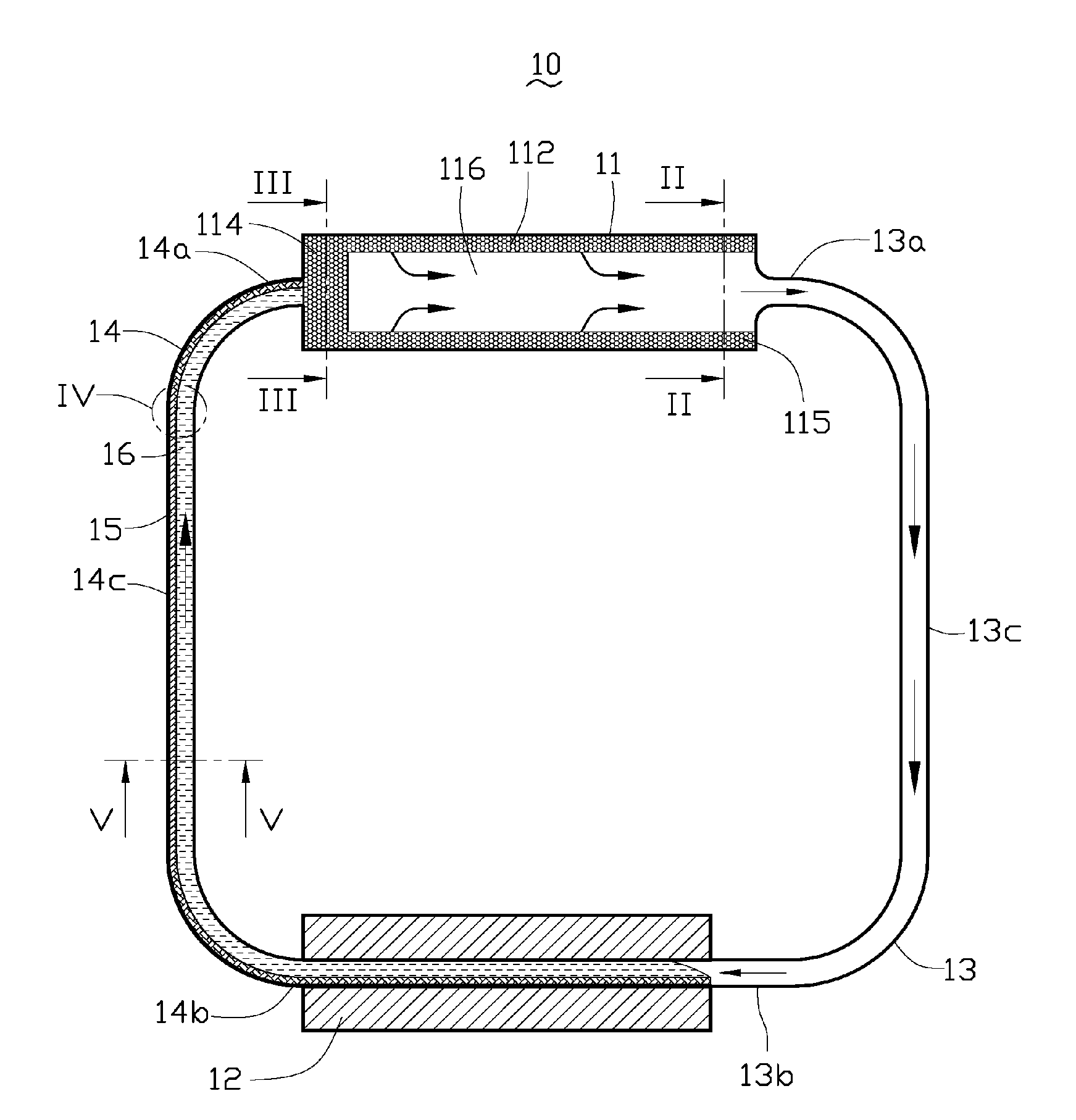
[0017]FIG. 1 illustrates a loop heat pipe 10 in accordance with a first embodiment of the present invention. The loop heat pipe 10 includes an evaporator 11 thermally connected with a heat generating electronic component such as a CPU (not shown), a condenser 12 thermally connected with a heat dissipating component such as a heat sink (not shown), vapor and liquid lines 13, 14 connecting the evaporator 11 with the condenser 12 to form a closed loop, a predetermined quantity of bi-phase working medium (not labeled) contained in the closed loop, and a flexible interwoven artery mesh 15 disposed within the liquid line 14.

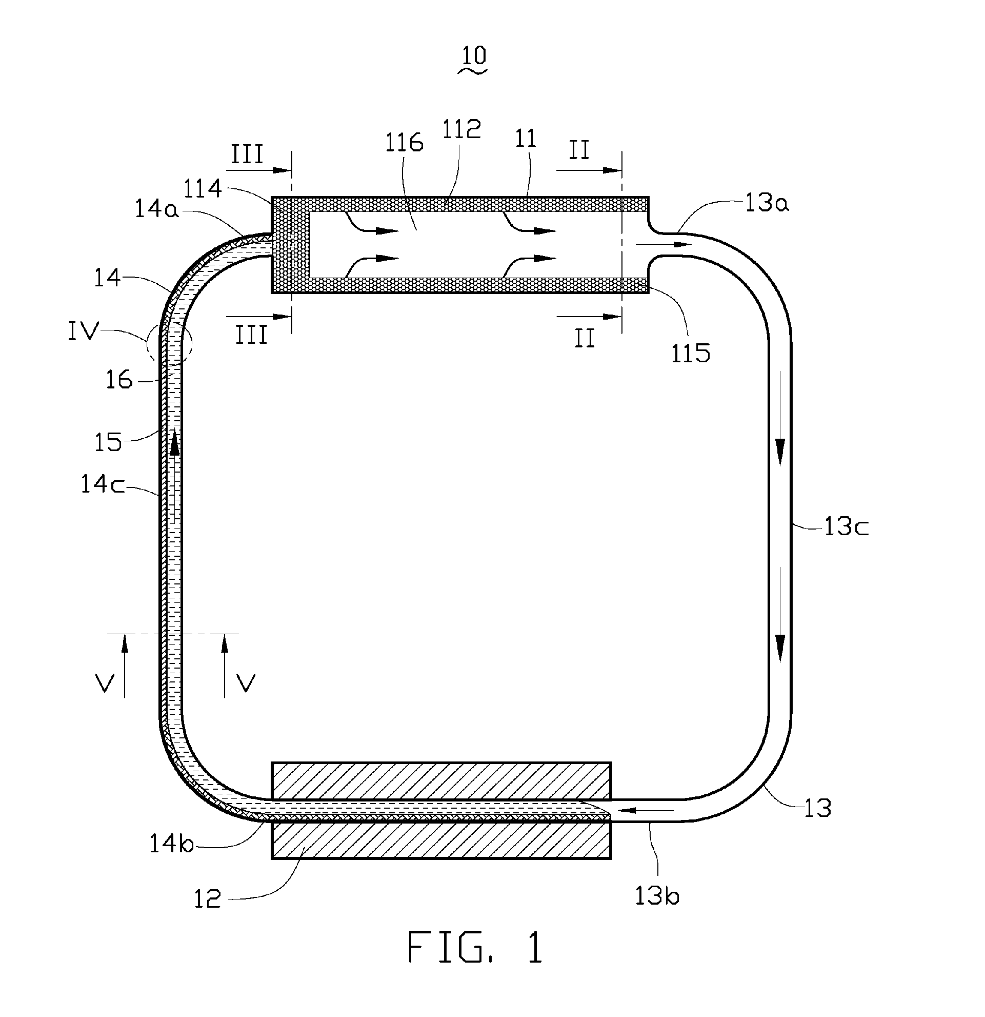
[0018]Referring particularly to FIGS. 2 and 3, the evaporator 11 is a hollow tube which contains a wick structure 112 coextensive with a central longitudinal axis of the evaporator 11. The wick structure 112 is tubular shaped in profile and has a column shaped outer wall 113 contacting with an inner wall of the evaporator 11. The wick structure 112 has a closed end 114...


PUM


Abstract

A loop heat pipe (10) includes an evaporator (11) thermally connected with a heat generating electronic component and including a wick structure (112) disposed therein, a condenser (12) thermally connected with a heat dissipating component, a vapor line (13) and a liquid line (14) connecting the evaporator with the condenser to form a closed loop, a predetermined quantity of bi-phase working medium contained in the closed loop, and an artery mesh (15) located within the liquid line.

Description

1. FIELD OF THE INVENTION[0001]The present invention relates generally to a loop heat pipe for transfer or dissipation of heat from heat-generating components, and more particularly to a loop heat pipe with flexible artery mesh disposed therein for improving heat dissipation for the heat-generating components.2. DESCRIPTION OF RELATED ART[0002]Loop heat pipes have excellent heat transfer performance due to their low thermal resistance, and are therefore an effective means for transfer or dissipation of heat from heat-generating components such as central processing units (CPUs) of computers.[0003]A conventionally loop heat pipe includes an evaporator thermally connected with a CPU and disposing a wick structure therein, a condenser thermally connected with a heat sink, a vapor line and a liquid line disposed between and connecting the evaporator with the condenser, a compensation disposed between the wick structure and the liquid line, and a predetermined quantity of bi-phase workin...

Claims


Application Information

Patent Timeline
IPC IPC(8): F28D15/04F28D15/00
CPCF28D15/043H01L23/427H01L2924/0002H01L2924/00
Inventor CHANG, CHANG-SHENLIU, JUEI-KHAIWANG, CHAO-HAOPEI, HSIEN-SHENG
Owner HON HAI PRECISION IND CO LTD
Why Eureka
Try Eureka