
Stereoscopic display apparatus

a display apparatus and stereoscopic technology, applied in the direction of electrical apparatus, instruments, optics, etc., can solve the problems of poor character display quality, insufficient fusion of beams from the sub-pixel, and difficult to display full color motion images using the principle of holograms

Inactive Publication Date: 2008-04-03
KK TOSHIBA
View PDF14 Cites 93 Cited by
  • Summary
  • Abstract
  • Description
  • Claims
  • Application Information

AI Technical Summary

Benefits of technology

[0010]A stereoscopic display apparatus according to the present invention has a display including pixels arrayed in a longitudinal direction and a lateral direction to form a matrix, each pixel comprising sub-pixels with color components, and a control element opposed to the display and including linear openings extendin

Problems solved by technology

Among stereoscopic motion image display apparatuses of this type, a scheme that utilizes the principle of hologram is difficult to display a full color motion image.
This method, however, displays longitudinal lines in a zigzag manner when displaying a stereoscopic image to particularly result in poor character display quality.
However, not only to solve the moiré but also to achieve continuous motion parallax as in the 1D IP scheme, with the conventional methods, the fusion of the beam from the sub-pixel is insufficient.
As described above, in the conventional stereoscopic display apparatus in which the beam control element is set vertically, moiré that interferes with display tends to occur readily to make it difficult to obtain continuous motion parallax.

Method used


Image

  • Stereoscopic display apparatus
  • Stereoscopic display apparatus
  • Stereoscopic display apparatus

Examples


Embodiment Construction

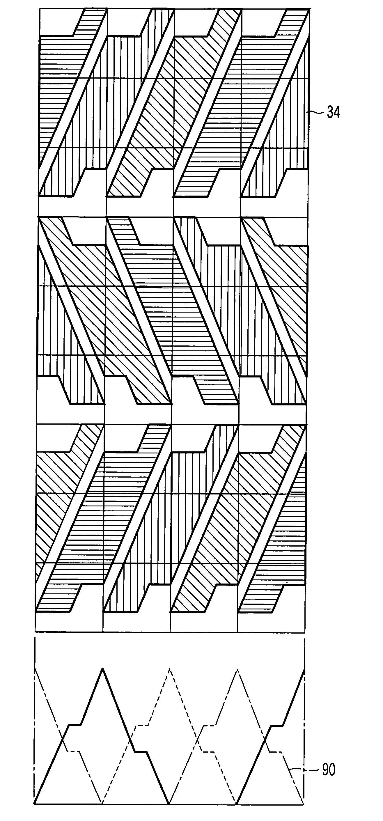
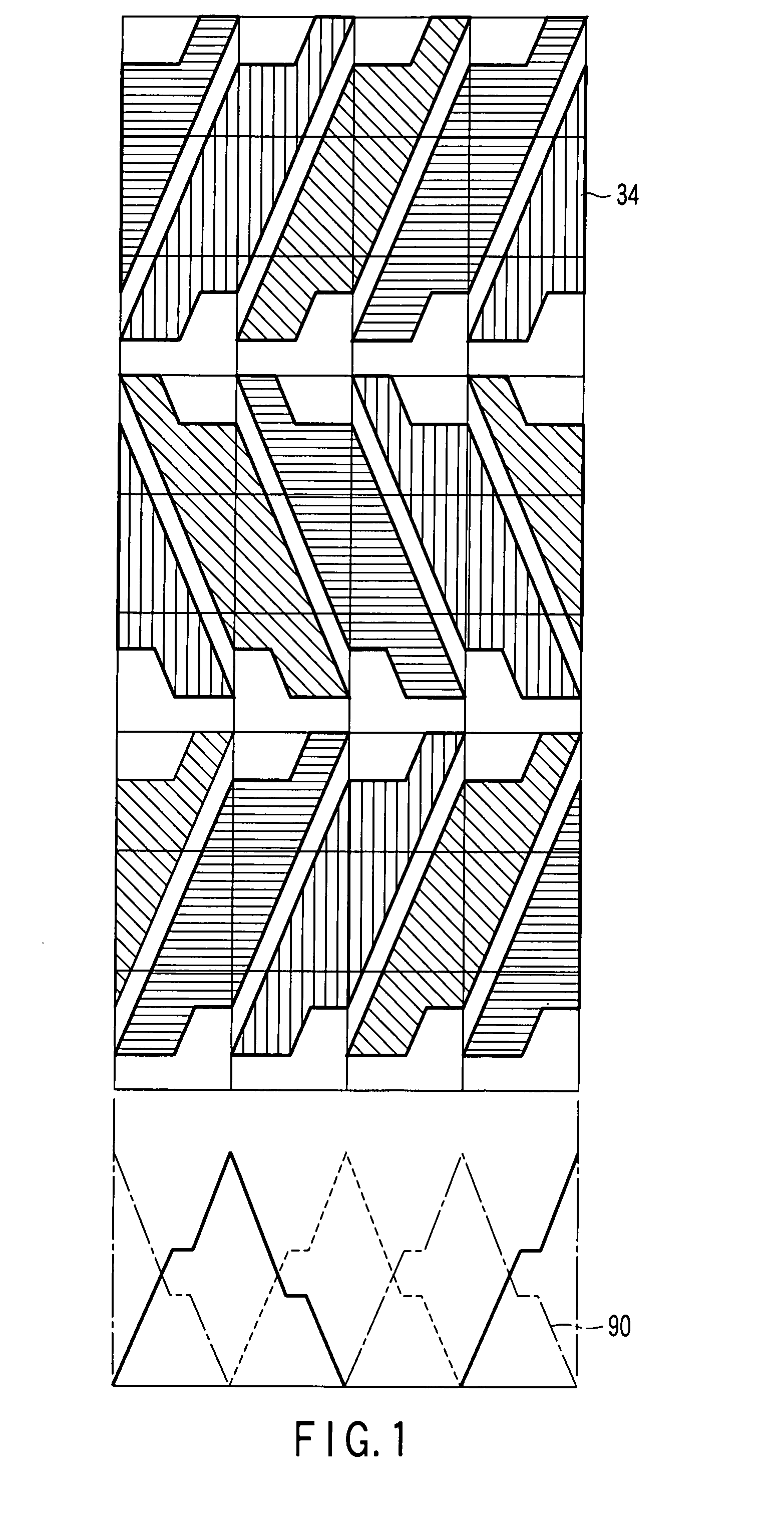
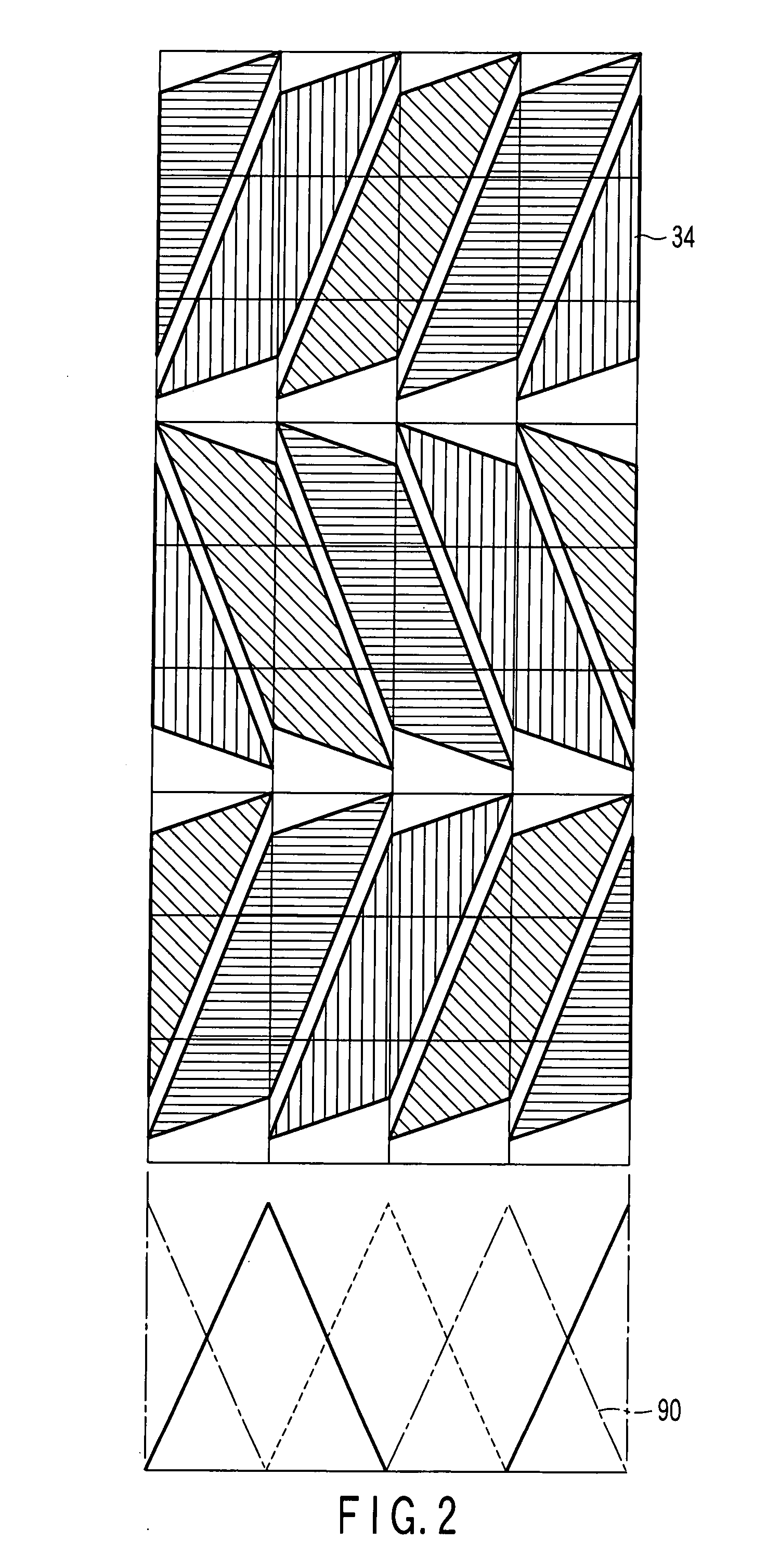
[0024]Referring to FIG. 1, squares are drawn as auxiliary lines, shaded portions indicate openings 34 (identical types of shaded portions indicate identical color components) of sub-pixels, and a plain white portion indicates a light-shield (black matrix). In the opening shape and the color arrangement of the sub-pixels in FIG. 1, light-shielding portions corresponding to longitudinal wiring lines (signal wiring lines) extend in a zigzag fashion in the column direction bending for every row. The light-shielding portions completely traverse the width (one square drawn as the auxiliary line) corresponding to the lateral period of sub-pixels in each row. According to this opening shape, openings 34 of any two sub-pixels adjacent in the lateral direction always overlap regardless of a position in the lateral direction. Furthermore, as shown in the lower portion of FIG. 1, the sum of longitudinal components 90 of the opening ratios (vertical opening ratios) of sub-pixels adjacent in the ...


PUM


Abstract

A stereoscopic display apparatus includes a display having pixels arrayed in a longitudinal direction and a lateral direction to form a matrix, each pixel including sub-pixels with color components, and a control element opposed to the display and having linear openings extending in the longitudinal direction and arrayed in the lateral direction. The openings of any two sub-pixels adjacent in the lateral direction always overlap regardless of a position in the lateral direction. The sum of the longitudinal components of the opening ratios of s adjacent in the lateral direction is constant.

Description

CROSS-REFERENCE TO RELATED APPLICATIONS[0001]This application is based upon and claims the benefit of priority from prior Japanese Patent Application No. 2006-272090, filed Oct. 3, 2006, the entire contents of which are incorporated herein by reference.BACKGROUND OF THE INVENTION[0002]1. Field of the Invention[0003]The present invention relates to a stereoscopic display apparatus.[0004]2. Description of the Related Art[0005]A stereoscopic image display apparatus capable of displaying a motion image, i.e., a so-called 3D display, is available in a variety of schemes. Particularly, in recent years, a demand increases for a scheme of a flat panel type that does not require exclusive eyeglasses. Among stereoscopic motion image display apparatuses of this type, a scheme that utilizes the principle of hologram is difficult to display a full color motion image. Another scheme in which a beam control element controlling a beam from the display panel and directing the beam toward the observe...

Claims


Application Information

Patent Timeline
IPC IPC(8): G09G3/20G02B30/27G02B30/30
CPCG02B27/2214G02B30/27G02B30/30H04N13/00
Inventor SAISHU, TATSUOFUKUSHIMA, RIEKOTAIRA, KAZUKIHIRAYAMA, YUZO
Owner KK TOSHIBA
Learn More