Display device and method of driving the same

a technology of a display device and a drive mechanism, applied in the direction of electric digital data processing, instruments, computing, etc., can solve the problems of constant power consumption due to voltage transition, waste during power consumption, etc., and achieve the effect of reducing power consumption

Active Publication Date: 2015-05-28
LG DISPLAY CO LTD
View PDF11 Cites 20 Cited by
  • Summary
  • Abstract
  • Description
  • Claims
  • Application Information

AI Technical Summary

Benefits of technology

[0013]According to the present invention as set forth above, it is possible to minimize power consumption since the display panel operates in the driving mode that changes depending on an image signal of the display device.

Problems solved by technology

Therefore, although an input image may be almost still, as in a document, power consumption constantly occurs due to voltage transition or data transition.
In particular, although the inversion driving and the driving speed are main reasons for power consumption in LCDs, they are always constant regardless of the types of image signals, thereby sometimes causing waste during power consumption.

Method used


Image

  • Display device and method of driving the same
  • Display device and method of driving the same
  • Display device and method of driving the same

Examples


first embodiment

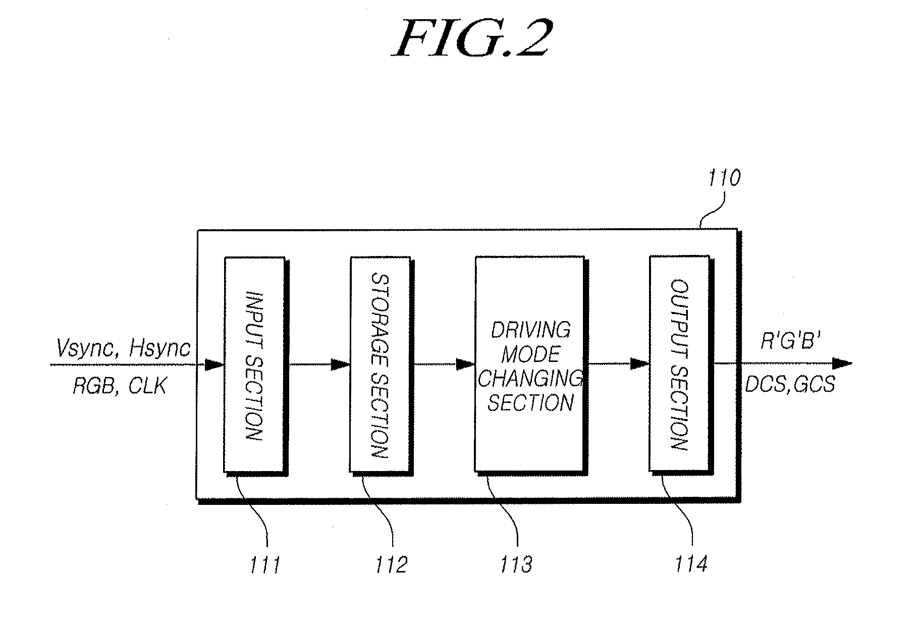
[0052]FIG. 2 is a detailed view showing an exemplary embodiment of the timing controller shown in FIG. 1.

[0053]Referring to FIG. 2, the timing controller 110 includes a input section 111 which receives timing signals Vsync, Hsync and DE and an image signal RGB transmitted from the host system 150, a storage section 112 which stores the image signals received from the input section 111, a driving mode changing section 113 which analyzes the image signals and changes a driving mode depending on the image signals, and an output section 114 which outputs image signals and control signals according to the changed driving mode to the display panel 140.

[0054]As described above, when the display panel 140 is an LCD panel, the driving mode changing section 113 changes inversion driving from among dot inversion, line inversion and frame inversion.

[0055]The LCD panel 140 drives the liquid crystal sandwiched between the first and second substrates by alternately charging and holding a voltage. ...

second embodiment

[0071]FIG. 5 is a detailed view showing another exemplary embodiment of the timing controller shown in FIG. 1.

[0072]Referring to FIG. 5, the timing controller 110 includes a input section 111 which receives timing signals and image signals transmitted from the host system 150, a storage section 112 which stores the image signals received from the input section 111, a driving mode changing section 113 which analyzes the image signals and changes the driving mode depending on the image signals, and an output section 114 which outputs image signals and control signals according to the changed driving mode to the display panel 140. The timing controller 110 also includes a clock generator 115 which generates a first clock acting as a standard clock and a second clock acting as a reference clock and a multiplexer (MUX) 115 which outputs one signal from among the image signals and control signals, which are inputted from the input section 111, and the image signals and the control signals...

third embodiment

[0077]In a third exemplary embodiment, the driving mode changing section 113 can change the drive frequency of an Nth frame depending on the complexity of image signals within the Nth frame.

[0078]Theoretically, flickering in an image may originate from different levels of voltage transition since pixels included in the image have different pixel values. At 60 Hz, even if the variation is very small due to the optimization of a common voltage, it may be noticeable when the drive frequency is high. When the drive frequency is reduced, the optimum position of the common voltage also changes. The low drive frequency causes even a minute variation to be clearly observed. When different gray scales are scattered on the screen, flickering becomes evident due to deviations in which the gray scales have different optimum common voltages. Therefore, the driving mode changing section 113 produces a proper drive frequency by calculating the complexity and setting a suitable range of the complex...


PUM


Abstract

A display device and a method of driving the same. The display device includes a display panel on which a plurality of data lines and a plurality of gate lines intersect each other to form a matrix, with a number of pixels being defined at intersections of the plurality of data lines and the plurality of gate lines. A data driver is connected to the plurality of data lines. A gate driver is connected to the plurality of gate lines. A timing controller controls the display panel to operate in a driving mode that changes depending on image signals.

Description

CROSS REFERENCE TO RELATED APPLICATION[0001]This application claims priority from and the benefit under 35 U.S.C. §119(a) of Korean Patent Application Number 10-2013-0144109 filed on Nov. 25, 2013, which are hereby incorporated by reference for all purposes as if fully set forth herein.BACKGROUND[0002]1. Field of the Invention[0003]The present disclosure relates to a display device and a method of driving the same.[0004]2. Description of Related Art[0005]In response to the growth of the information society, there is an increasing demand for various types of image display devices. Currently, various display devices such as liquid crystal displays (LCDs), plasma display panels (PDPs) and organic light-emitting diode displays (OLEDs) are used.[0006]Display devices such as LCDs and OLEDs drive a panel at a fixed drive frequency regardless of the type of input image. Therefore, although an input image may be almost still, as in a document, power consumption constantly occurs due to volta...

Claims


Application Information

Patent Timeline
Patent Type & Authority Applications(United States)
IPC IPC(8): G09G3/36
CPCG09G3/3614G09G3/3607G09G2310/08G09G2330/023G09G2310/06G09G2320/0247G09G2320/0257G09G2320/103G09G2330/021
Inventor LEE, SUNGGAEHONG, HEEJUNGLEE, DONG-WOO
Owner LG DISPLAY CO LTD
Why Eureka
Try Eureka