Relay apparatus, relay method, and relay program

a relay and relay technology, applied in the field of relay apparatus, relay method, relay program, can solve the problems of packet transmission failure, high packet transmission error rate, delay in transmission of communication data of another wireless terminal,

Inactive Publication Date: 2008-04-03
FUJITSU LTD
View PDF7 Cites 126 Cited by
  • Summary
  • Abstract
  • Description
  • Claims
  • Application Information

AI Technical Summary

Benefits of technology

[0010]The retransmission adjusting part determines the upper limit of the packet retransmission number in accordance with the amount of the available bandwidth obtained by excluding the total bandwidth in use calculated based on the data obtained by the packet monitoring part from the maximum bandwidth available in the radio communication. Therefore, the upper limit of the number of retransmissions adaptable to the entire use situation of a bandwidth for the radio communication in the communication area is determined. The retransmitting part retransmits a packet whose transmission has ended in failure by the relay apparatus based on the upper limit of the number of retransmissions determined by the retransmission adjusting part. Therefore, the retransmission appropriately adaptable to the entire use situation of a bandwidth can be performed. Consequently, the communication quality of the radio communication by the wireless terminal in the communication area of the relay apparatus can be enhanced.
[0025]According to the above configuration, regarding the prioritized communication in which a packet is relayed by priority by the priority relaying part, the packet can be retransmitted in a range not exceeding an upper limit of the packet retransmission number in accordance with the use situation of a bandwidth, and regarding the non-prioritized communication other than the prioritized communication, the number of retransmissions corresponding to the previously determined number can be ensured. Therefore, in the prioritized communication, the number of retransmissions is suppressed from increasing to cause the delay due to an insufficient bandwidth. On the other hand, in the non-prioritized communication, although the possibility of the occurrence of a delay increases compared with the prioritized communication, the number of retransmissions is ensured, so that the occurrence of a packet loss is suppressed.

Problems solved by technology

Furthermore, generally, in radio communication between a wireless terminal and a relay apparatus, a packet transmission error rate is high due to the influence by an obstacle and the like.
When a packet is retransmitted, a bandwidth in use increases accordingly, and when a bandwidth in use exceeds the capacity of transmission which relay apparatus manages, transmissions of radio terminals and relay apparatus interfere each other, and tend to end in failures.
Consequently, the transmission of communication data of another wireless terminal may be delayed.
Furthermore, during an off-peak time in which only one wireless terminal performs communication in a communication area, in spite of the fact that there is a sufficient available bandwidth for retransmissions, retransmissions of a previously set upper limit value or more cannot be performed, resulting in a packet transmission failure.
According to the above-mentioned conventional method, since the entire use situation of a bandwidth for radio communication by wireless terminals in a communication area is not taken into consideration, the above-mentioned circumstances cannot be prevented.

Method used


Image

  • Relay apparatus, relay method, and relay program
  • Relay apparatus, relay method, and relay program
  • Relay apparatus, relay method, and relay program

Examples


embodiment 1

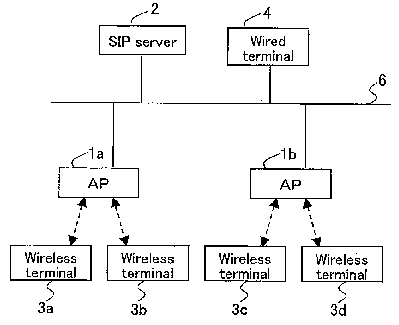
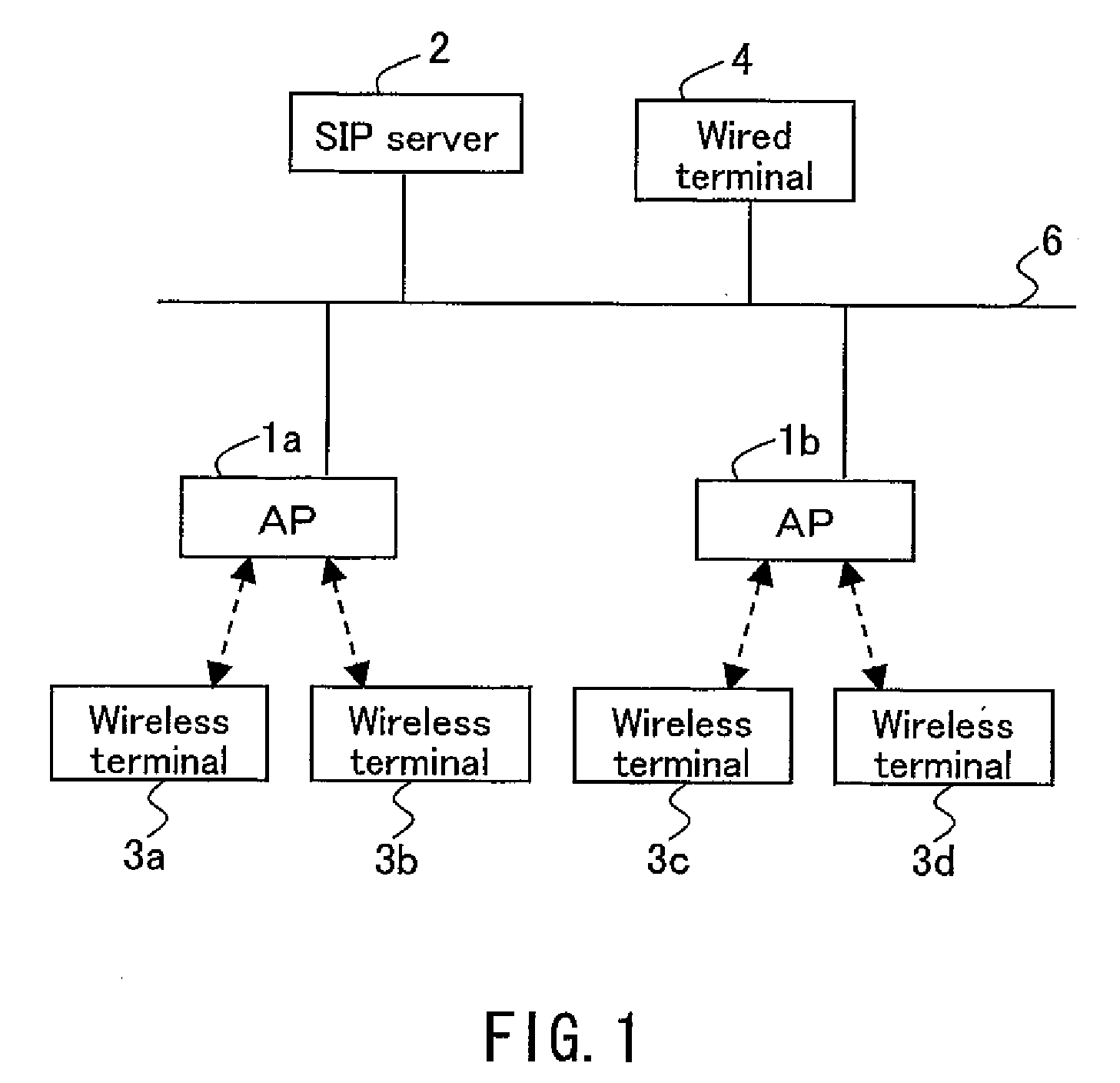
[0053]Embodiment 1 is the case where a relay apparatus is a wireless LAN access point (hereinafter, referred to as an “AP”), as an example. FIG. 1 is a functional block diagram showing a configuration of APs according to the present embodiment together with a function of an entire communication system including the APs. The communication system shown in FIG. 1 enables the communication by wireless IP telephones using a wireless LAN, for example.

[0054]The communication system shown in FIG. 1 includes an AP 1a, an AP 1b, a session initiation protocol (SIP) server 2, and a wired terminal 4 that are connected to a wired LAN 6, wireless terminals 3a, 3b in a communication area of the AP 1a, and wireless terminals 3c, 3d in a communication area of the AP 1b. The wireless terminals 3a, 3b and the wired terminal 4 have a function of an IP telephone terminal. The number of APs connected to the wired LAN 6 is not limited to two as shown in FIG. 1. Furthermore, the number of wireless terminals...

embodiment 2

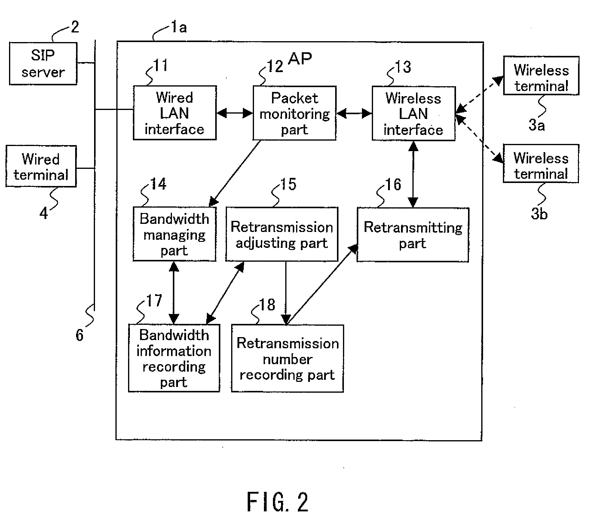
[0100]In the present embodiment, the function of controlling a packet retransmission at a wireless terminal is added to Embodiment 1, FIG. 10 is a functional block diagram showing a configuration of the AP 10a according to the present embodiment. In FIG. 10, the same functional blocks as those in FIG. 2 are denoted with the same reference numerals as those therein, and the description thereof will be omitted. The AP 10a shown in FIG. 10 further includes a beacon generating part 23. Furthermore, the wireless terminal 30a includes a wireless LAN interface 24, a beacon analyzing part 25, a retransmission number setting part 26, a retransmission number recording part 18a, and a retransmitting part 16a. a wireless terminal 30b can also have a similar configuration.

[0101]The beacon generating part 23 of the AP 10a notifies the wireless terminals 30a, 30b of the upper limit of the number of retransmissions determined by the retransmission adjusting part 15, using a beacon. The beacon gener...

embodiment 3

[0107]FIG. 11 is a functional block diagram showing a configuration of an AP 100a according to the present embodiment. In FIG. 11, the same functional blocks as those in FIG. 2 are denoted with the same reference numerals as those therein, and the description thereof will be omitted. An AP 100a shown in FIG. 11 further includes a retransmission history recording part 31. The retransmitting part 16a has a function that is not present in the retransmitting part 16 shown in FIG. 2. The retransmitting part 16a determines a transmission interval at which a packet is retransmitted with reference to the retransmission history recording part 31, and retransmits a packet at the determined transmission interval. The retransmission history recording part 31 records a retransmission timing of a packet and a packet transmission success rate at that retransmission timing in such a manner that they are associated with each other. It is preferable that, every time the retransmitting part 16a retran...


PUM


Abstract

A relay apparatus for relaying a packet in radio communication by a wireless terminal in a communication area includes a packet monitoring part for obtaining data on a bandwidth to be used in the radio communication by the wireless terminal from a packet to be relayed, a bandwidth managing part for calculating and recording a total bandwidth in use used for the radio communication by the wireless terminal from the obtained data on a bandwidth, a retransmission adjusting part for determining an upper limit of a packet retransmission number, in accordance with an amount of an available bandwidth obtained by excluding a total bandwidth in use from a maximum bandwidth, and a retransmitting part for retransmitting a packet in a range not exceeding the upper limit of the packet retransmission number. Consequently, the relay apparatus enables retransmission appropriately adaptable to a use situation of a bandwidth by wireless communication of a wireless terminal in a communication area.

Description

BACKGROUND OF THE INVENTION[0001]1. Field of the Invention[0002]The present invention relates to a relay apparatus for relaying, in a limited bandwidth, communication by a plurality of wireless terminals in a communication area, for example, as in access points in a wireless local area network (LAN).[0003]2. Description of Related Art[0004]Recently, for example, as in an IP telephone via a wireless LAN, a wireless terminal that performs a telephone conversation via radio communication has become widespread. The wireless terminal that performs a telephone conversation via radio communication enables a telephone conversation with a terminal on a partner side by performing radio communication with a relay apparatus (e.g., an access point of a wireless LAN, etc.). In such a communication form, a plurality of wireless terminals are present in a communication area of a relay apparatus, whereby simultaneous telephone conversations by the wireless terminals occur. In this case, the pluralit...

Claims


Application Information

Patent Timeline
Patent Type & Authority Applications(United States)
IPC IPC(8): H04B7/14G01R31/08H04L12/26G06F11/00H04L12/801H04L12/911H04W4/00H04W28/00H04W28/04
CPCH04L2001/0092H04L1/1887
Inventor SUMIOKA, MOTOSHIMATSUKURA, RYUICHIFUJIMOTO, SHINGO
Owner FUJITSU LTD
Why Eureka
Try Eureka