Screw with a drilling tail

a drilling tail and screw technology, applied in the direction of screws, threaded fasteners, fastening means, etc., can solve the problems affecting the force needed to be applied in operation, and achieve the effect of quickly and effectively removing dregs in operation

Inactive Publication Date: 2008-04-03
LIN TENG HUNG
View PDF6 Cites 41 Cited by
  • Summary
  • Abstract
  • Description
  • Claims
  • Application Information

AI Technical Summary

Benefits of technology

[0004]Accordingly, the primary object of the present invention is to provide a scre

Problems solved by technology

It also affects the force neces

Method used


Image

  • Screw with a drilling tail
  • Screw with a drilling tail
  • Screw with a drilling tail

Examples


Embodiment Construction

[0015]In order that those skilled in the art can further understand the present invention, a description will be provided in the following in details. However, these descriptions and the appended drawings are only used to cause those skilled in the art to understand the objects, features, and characteristics of the present invention, but not to be used to confine the scope and spirit of the present invention defined in the appended claims.

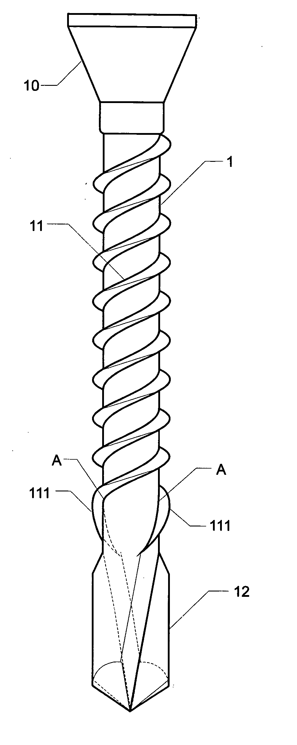
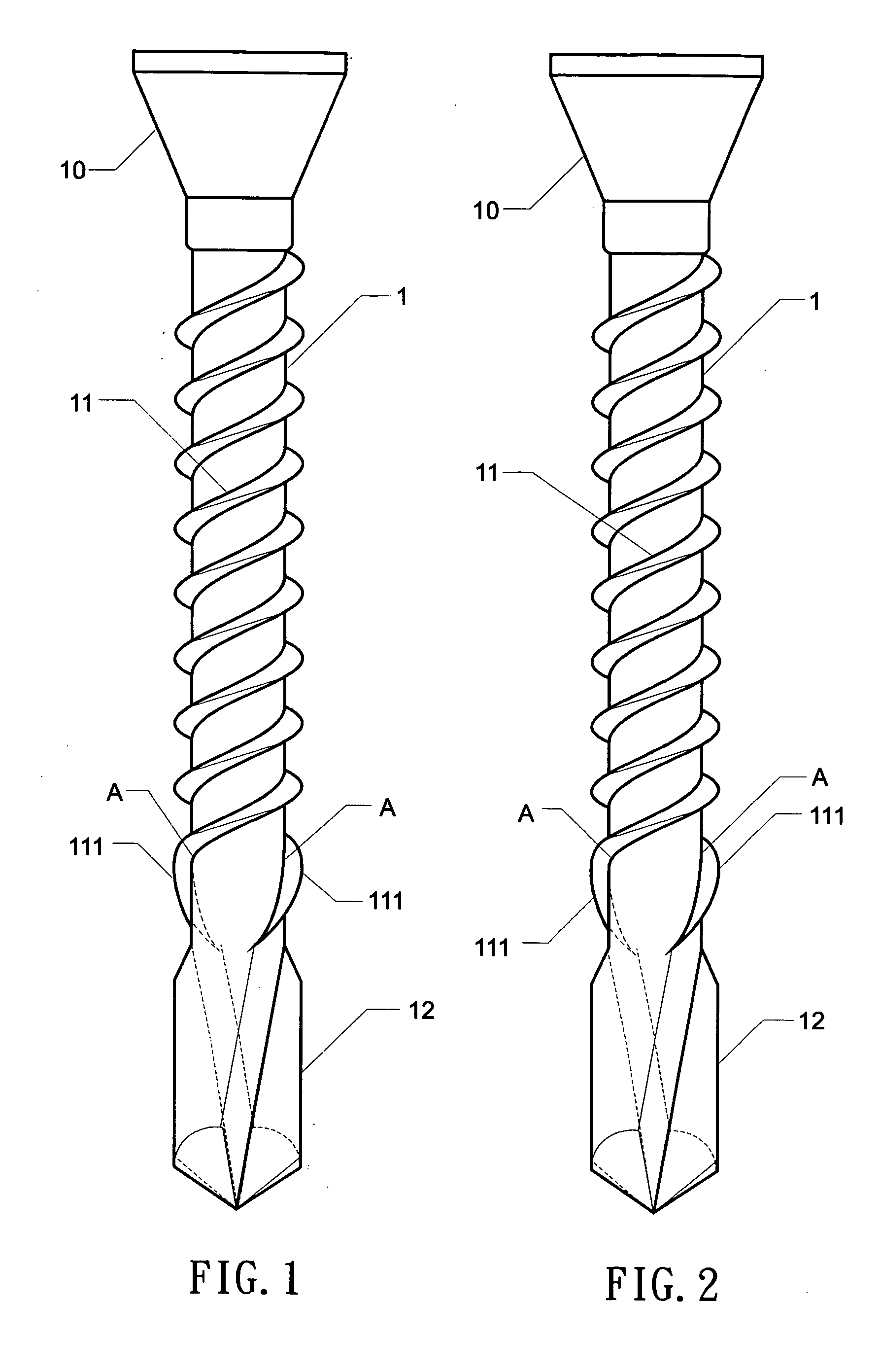
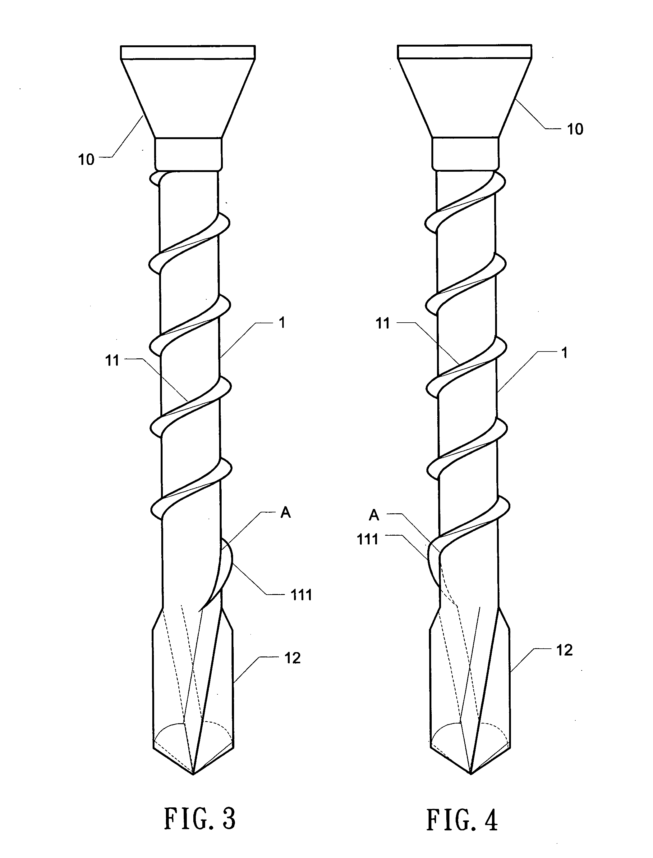
[0016]Referring to FIGS. 1 to 3, the screw with a drilling tail is illustrated. The present invention has the following elements.

[0017]In FIGS. 1 and 2, the screw has a screw head 10, a drilling tail 12, a rod portion 1 between the screw head 10 and the drilling tail 12, and two threads 11 on the rod portion 1. The helix angle A at one end of each thread 11 near the drilling tail 12 becomes larger than the helix angle at other portion of the thread 11 so as to form a guide thread section 111 which covers a range not over half circle of the rod port...


PUM


Abstract

A screw with a drilling tail comprises: a screw head, a drilling tail, a rod portion between the screw head and the drilling tail, and at least one first threads on the rod portion, wherein the helix angle at one end of each thread near the drilling tail becomes larger than the helix angle at other portion of the thread so as to form a guide thread section which covers a range not over half circle of the rod portion; and a distal end of the guide thread section is at an upper end of the drilling tail. There is one or two first threads. The screw with a drilling tail further comprises a second thread between the screw head and the at least one first thread.

Description

FIELD OF THE INVENTION[0001]The present invention relates to screws, and particularly to a screw with a drilling tail, which can remove dregs in operation quickly and effectively, wherein the helix angle at one end of each thread near the drilling tail becomes larger than the helix angle at other portion of the thread so as to form a guide thread section which covers a range not over half circle of the rod portion; and a distal end of the guide thread section is at an upper end of the drilling tail.BACKGROUND OF THE INVENTION [0002]To cause the screw to be screwed into an object quickly, the problem of removing the dregs is an important concern. It also affects the force necessary to be applied in operation. If the dregs are removed quickly, the twisting force is smaller. Thus there are many developments being aimed at the removing of dregs.[0003]In some improved designs, other threads which have forms different from the original threads are designed in some sections of the screws s...

Claims


Application Information

Patent Timeline
IPC IPC(8): F16B25/10
CPCF16B25/0031F16B25/0057F16B35/065F16B25/10F16B35/041F16B25/0073
Inventor LIN, TENG-HUNG
Owner LIN TENG HUNG
Why Eureka
Try Eureka