
Optimized design for a contact start-stop slider

Inactive Publication Date: 2008-04-10
SAMSUNG ELECTRONICS CO LTD
View PDF8 Cites 0 Cited by
  • Summary
  • Abstract
  • Description
  • Claims
  • Application Information

AI Technical Summary

Problems solved by technology

The drive may power down and power up numerous times. This creates repeated contact between the head and the disk that may deplete the lubricant on the landing track of the disk.

Method used


Image

  • Optimized design for a contact start-stop slider
  • Optimized design for a contact start-stop slider
  • Optimized design for a contact start-stop slider

Examples


Embodiment Construction

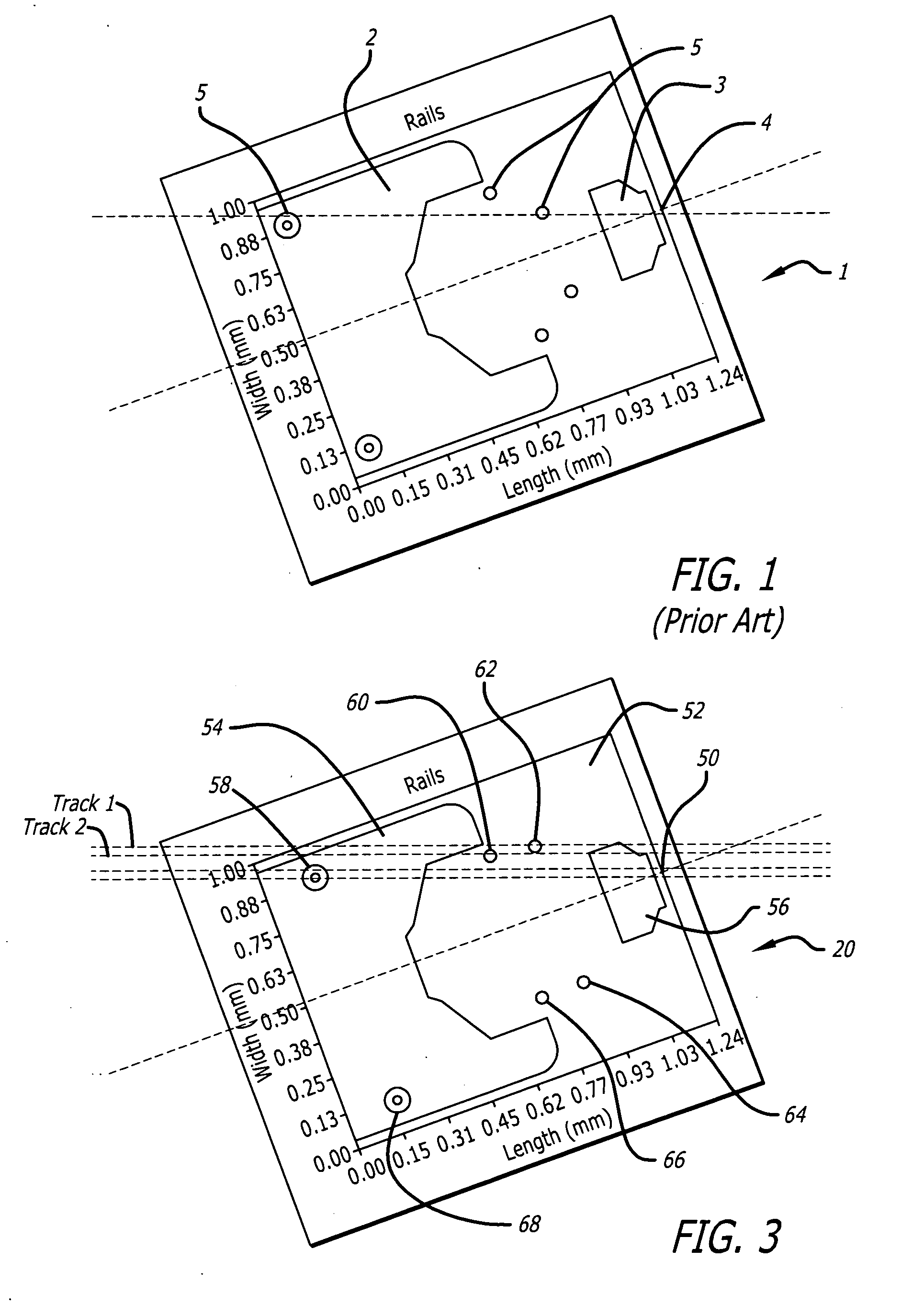
[0016]Disclosed is a head that flies relative to a disk of a hard disk drive. The head includes a substrate that has a pole tip, and an air bearing surface that has at least one rail and a central pad. The air bearing surface also has a plurality of contact dots that each make contact with the disk at different skew angles. Providing contact at different skew angles insures that multiple dots do not make contact with the same track of the disk. This is particularly advantageous when the head is landed on the disk at the same skew angle.

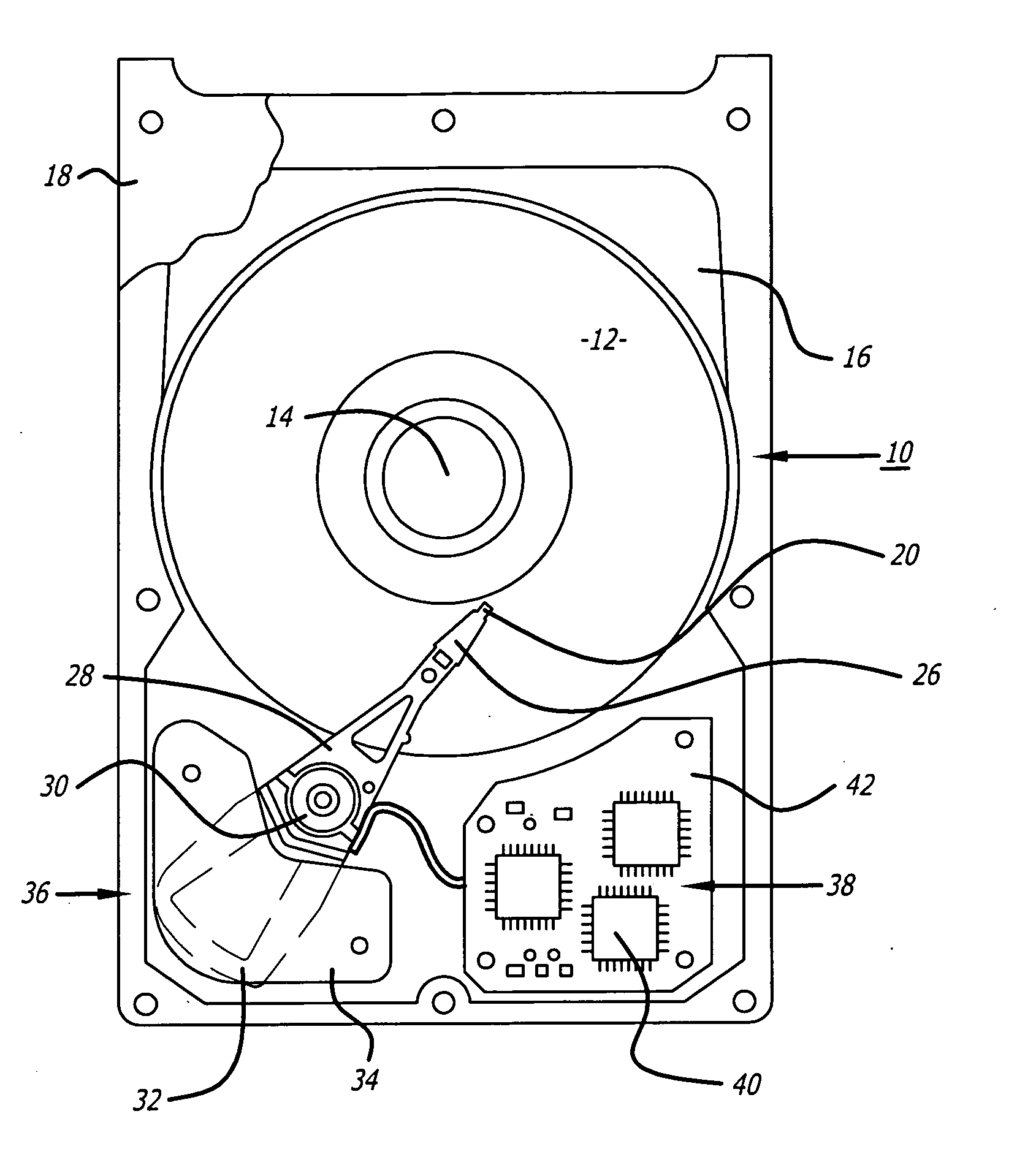
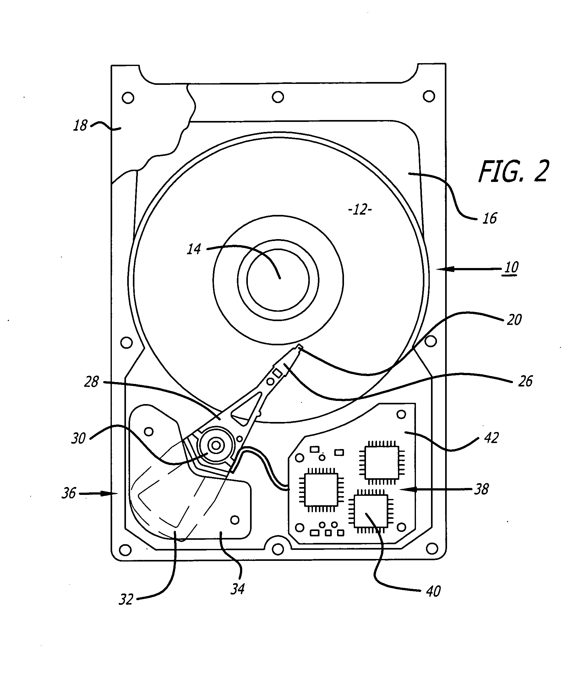
[0017]Referring to the drawings more particularly by reference numbers, FIG. 2 shows an embodiment of a hard disk drive 10. The disk drive 10 may include one or more magnetic disks 12 that are rotated by a spindle motor 14. The spindle motor 14 may be mounted to a base plate 16. The disk drive 10 may further have a cover 18 that encloses the disks 12. The disk drive 10 may include a plurality of heads 20 located adjacent to the disks 12.

[0018]Each hea...


PUM


Abstract

A head that flies relative to a disk of a hard disk drive. The head includes a substrate that has a pole tip, and an air bearing surface that has at least one rail and a central pad. The air bearing surface also has a plurality of contact dot that each makes contact with the disk at different skew angles. Providing contact at different skew angles insures that multiple dots do not make contact with the same track of the disk. This is particularly advantageous when the head is landed on the disk at the same skew angle.

Description

BACKGROUND OF THE INVENTION[0001]1. Field of the Invention[0002]The present invention relates to an air bearing surface of a head in a hard disk drive.[0003]2. Background Information[0004]Hard disk drives contain a plurality of magnetic heads that are coupled to rotating disks. The heads write and read information by magnetizing and sensing the magnetic fields of the disk surfaces. Each head is attached to a flexure to create a subassembly commonly referred to as a head gimbal assembly (“HGA”). The HGA's are suspended from an actuator arm. The actuator arm has a voice coil motor that can move the heads across the surfaces of the disks.[0005]In operation, each head is separated from a corresponding disk surface by an air bearing. The air bearing minimizes the mechanical wear between the head and the disk. The strength of the magnetic field is inversely proportional to the height of the air bearing. A smaller air bearing results in a stronger magnetic field on the disks, and vice vers...

Claims


Application Information

Patent Timeline
IPC IPC(8): G11B5/60
CPCG11B5/6005G11B5/54G11B5/6082
Inventor CHEN, CHAO YUANSULLIVAN, MICHAEL
Owner SAMSUNG ELECTRONICS CO LTD
Learn More