
Utility knife with integrated hole punch

Inactive Publication Date: 2008-04-17
PARKS THOMAS JERALD
View PDF23 Cites 37 Cited by
  • Summary
  • Abstract
  • Description
  • Claims
  • Application Information

AI Technical Summary

Benefits of technology

[0017]The multipurpose utility knife of the present invention provides a utility knife with an integrated hole punch and comprises a body, a cutting blade, a spare blade holder, a hole punch arm, a hole punch recess, a hole punch bit, a confetti storage cavity, a confetti removal door, and a spare blade holder. The present invention may be constructed from various rigid structural materials such as plastic, metal, or epoxy resin. The present invention's compact size means that it may be comfortably carried in a pocket for easy access.
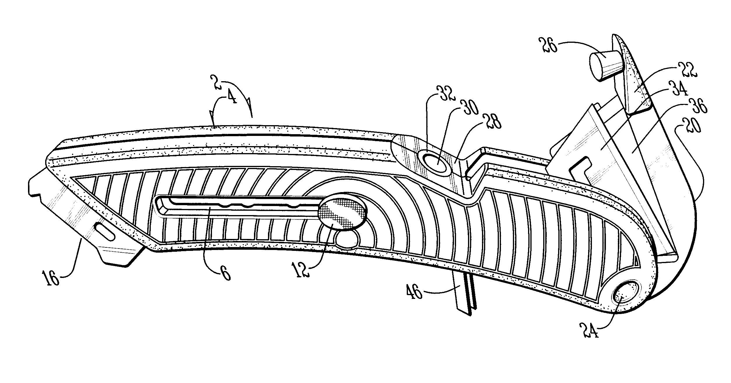
[0019]The present invention also allows a store employee to easily make a new display hanging hole in product packaging to allow a product with a defective or torn display hole to be hung from display pegs. To make a display hole with the present invention, a user selectively disables an optional hole punch lock and pivots a hole punch arm from a closed position to an open position. A user then positions the desired material within a receiving area defined between the hole punch arm and the body when the hole punch arm is pivoted to the open position. The user then applies sufficient pressure to the hole punch arm to complete a punch through the material. The present invention then forces the resulting confetti, i.e., the piece of material that is punched from the article, through the hole punch recess into a confetti storage cavity.

Problems solved by technology

One of the disadvantages of a typical utility knife is that the user can only utilize the tool as a cutting instrument.
However, in some situations, the hole is defective or does not exist, and a store employee cannot properly display the merchandise.
Further, the complexity of the '040 application will invariably drive manufacturing costs to such a level that the price of such a device is not competitive with the present invention.

Method used


Image

  • Utility knife with integrated hole punch
  • Utility knife with integrated hole punch
  • Utility knife with integrated hole punch

Examples

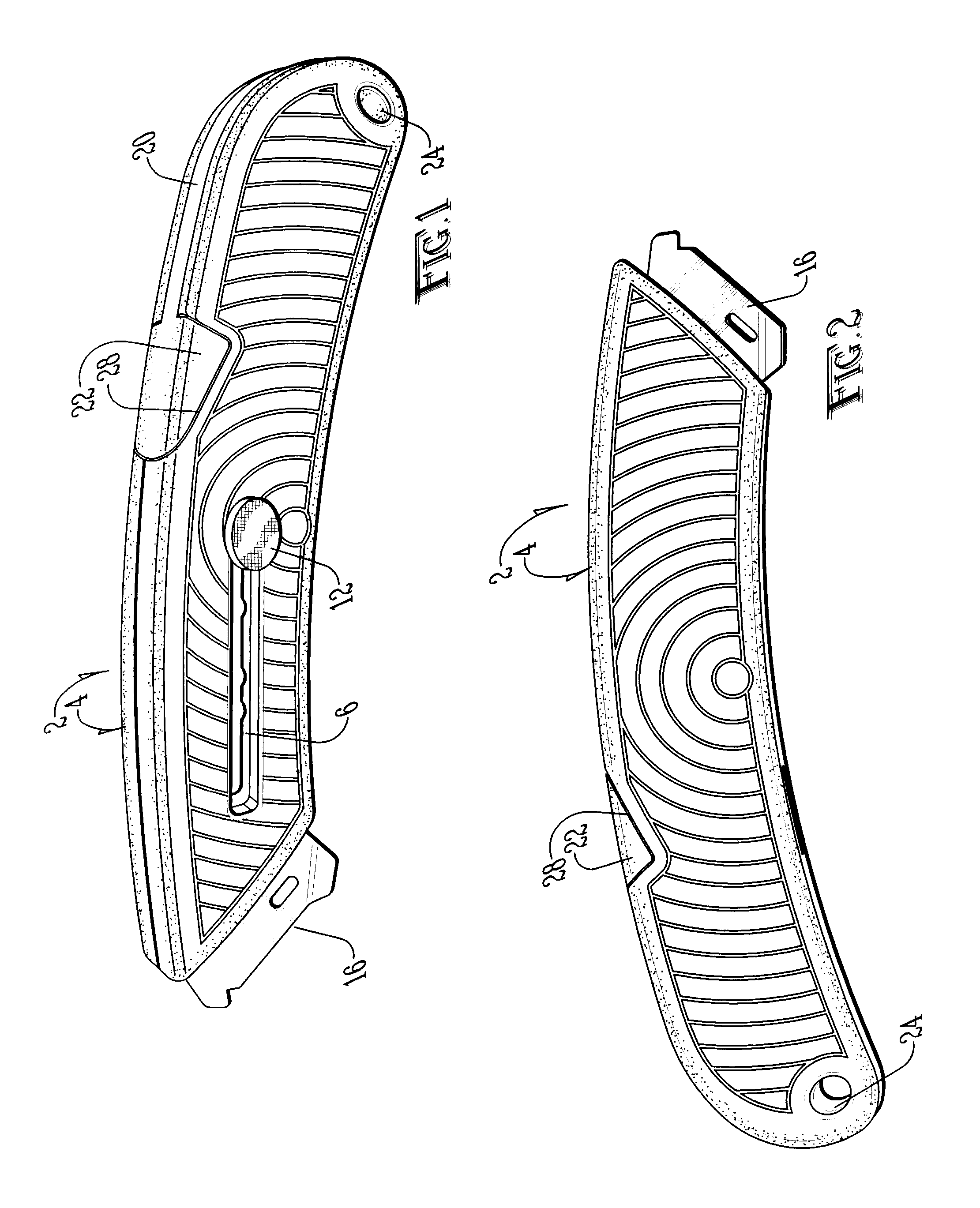
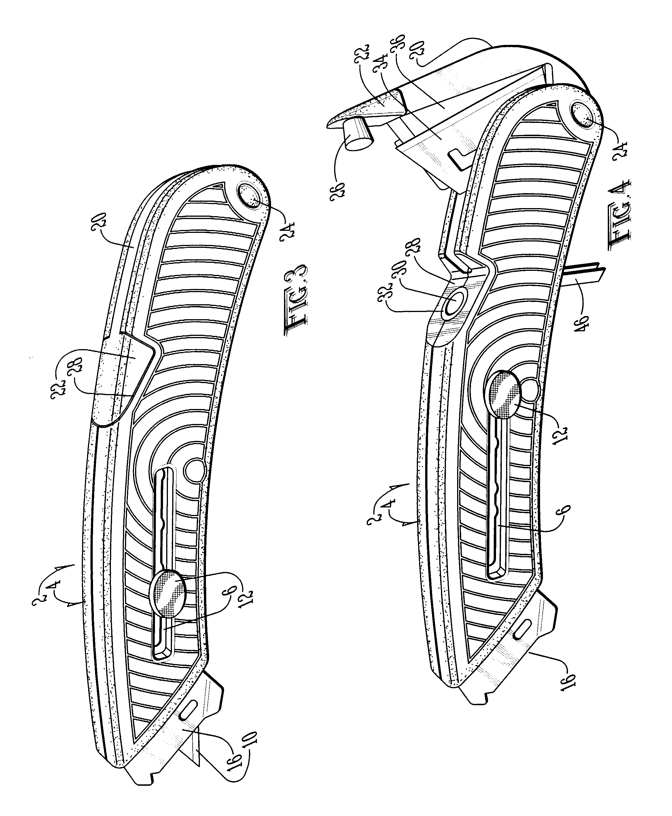

Embodiment Construction

[0028]The present invention discloses a utility knife that provides the heretofore unknown features of an integrated hole punch mechanism and an internal confetti storage cavity. The inventor believes that the present invention will be useful to retail store and other employees who routinely carry both a utility knife and a hole punch.

[0029]Referring generally to the figures, a utility knife 2 includes a body 4 that has a cutting blade recess 14 for storing a cutting blade holder 6. The cutting blade holder 6 is secured to the inside of the body 4 to prevent the cutting blade holder 6 from moving inside the body. A cutting blade 10 placed into the cutting blade holder 6 and secured into a recess between the two halves of body 4. A cutting blade slot 8 in the body 4 allows the cutting blade 10 to be extended from the body or to be retracted into the body 4.

[0030]FIG. 1 shows an exemplary utility knife according to the present invention designed for a right-handed user. A left-handed ...


PUM


Abstract

A utility knife in accordance with the present invention combines a cutting tool and a hole punch into a single compact, efficient tool. The utility knife includes a recess into which the cutting blade is retracted and another recess to store a hole punch. The hole punch pivots from one end the body so that a piece of material to be punched can be placed between the hole punch and the body. The hole punch is pivoted towards the body to punch through the material. The punch mechanism pushes confetti from the material into a confetti storage cavity within the body. A user can open the confetti storage door to discard the confetti stored within the body. The present invention also allows a user to store extra cutting blades within a recess in the hole punch arm.

Description

CROSS REFERENCES[0001]None.GOVERNMENTAL RIGHTS[0002]None.BACKGROUND OF THE INVENTION[0003]The present invention pertains generally to a multipurpose handheld tool and more particularly to a utility knife with an integrated hole punch that is easily operated using one hand.[0004]Retail store employees receive shipments, open boxes, sort through merchandise, and stock shelves and displays. As with most jobs, speed and efficiency are important considerations. Stock must be shelved quickly and neatly to provide sufficient turnover and income, and in the case of food products, speed may reduce the risk of spoliation. A tool commonly used by retail store employees is a cutting implement, usually referred to as a utility knife. A typical utility knife has a retractable blade and is used to cut shipping containers and packaging materials such as shrink-wrap, tape, and boxes to access the contents of the containers.[0005]One of the disadvantages of a typical utility knife is that the user ca...

Claims


Application Information

Patent Timeline
IPC IPC(8): B26B3/06F41B13/02
CPCB26B5/001B26F1/36B26D9/00B26B11/00
Inventor PARKS, THOMAS JERALD
Owner PARKS THOMAS JERALD
Learn More