Blind bottom rail having a labor-saving function

a technology of labor-saving function and bottom rail, which is applied in the direction of door/window protective devices, building components, constructions, etc., can solve the problems of labor-consuming operation and assembly inconvenience, and achieve the effect of convenient assembly

Inactive Publication Date: 2008-04-17
GUANGZHOU CARFORD DECORATION MATERIAL
View PDF7 Cites 22 Cited by
  • Summary
  • Abstract
  • Description
  • Claims
  • Application Information

AI Technical Summary

Benefits of technology

[0008]An object of the present invention is to provide a blind bottom rail, which can be easily assembled

Problems solved by technology

However, when the above blind 90 is in use, the whole bottom rail 93 will be led to move, hence causing labor-consuming oper

Method used


Image

  • Blind bottom rail having a labor-saving function
  • Blind bottom rail having a labor-saving function
  • Blind bottom rail having a labor-saving function

Examples


Embodiment Construction

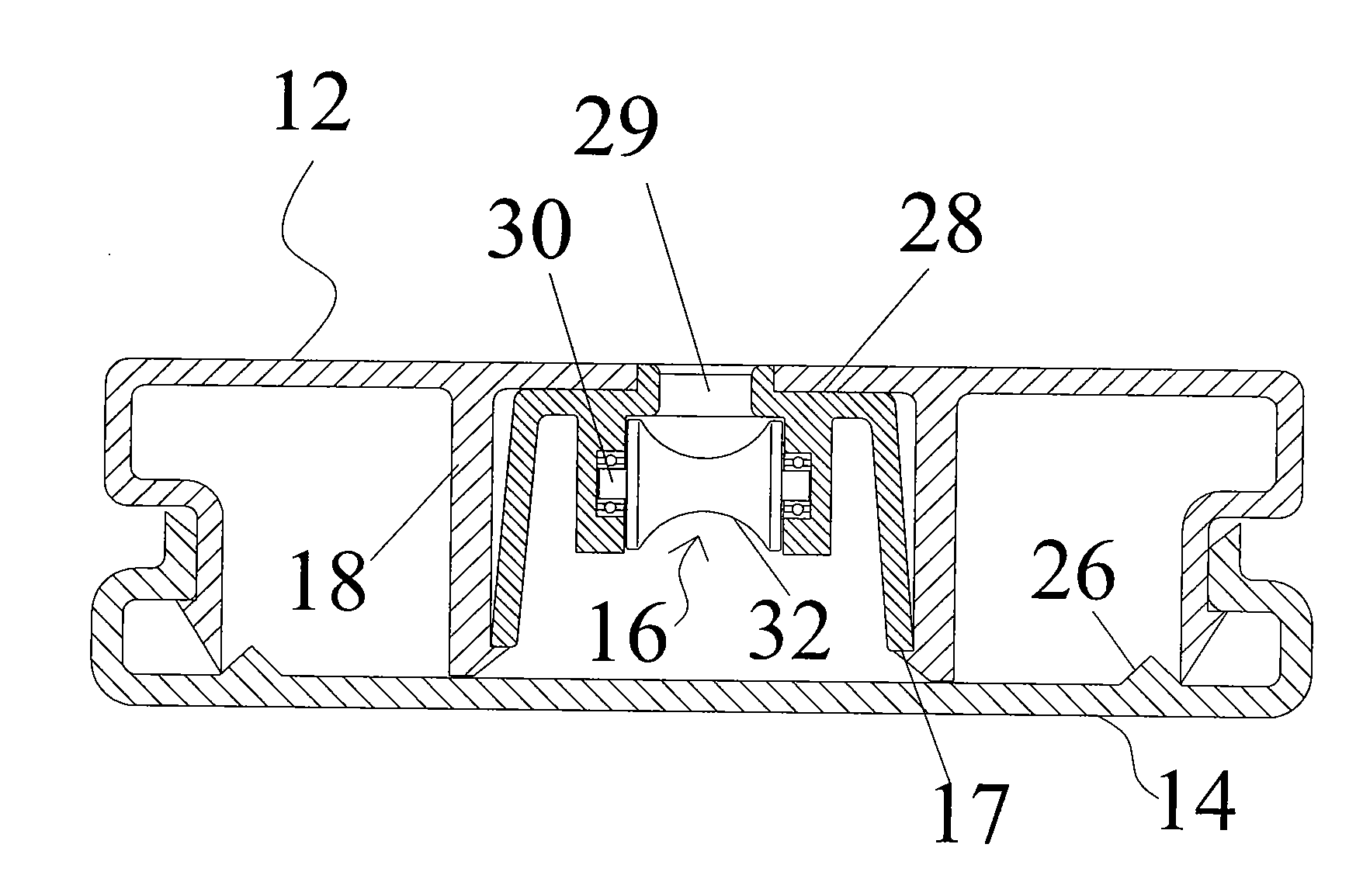
[0025]As shown in FIGS. 2 and 3, a blind bottom rail 10 having a labor-saving function comprises a first rail 12, a second rail 14 and several force-bearing devices 16. Two supporting portions 18 each having a locking hook 17 are disposed in the first rail 12 to form a receiving groove 20. Several through holes 22 are formed at the bottom of the receiving groove 20. Two hook bars 24 are respectively disposed at two outer sides of the first rail 12. The second rail 14 has two sides respectively corresponding to those of the first rail 12. Two fixing portions 26 are respectively disposed at two inner sides of the second rail 14. The first rail 12 is locked in the second rail 14 by using the fixing portions 26 and the hook bars 24. Reference is also made to FIGS. 4 and 5. The connection manner of the first rail 12 and the second rail 14 can be more clearly understood.

[0026]As shown in FIGS. 2, 3, 4 and 5, the force-bearing device 16 has a fixing seat 28 and a bearing 30. The fixing sea...


PUM


Abstract

A blind bottom rail having a labor-saving function comprises a first rail, a second rail and several force-bearing devices with a pulley. Two sides of the first and second rails correspond to each other to let the first rail be fixed in the second rail. Two supporting portions are disposed in the first rail to form a receiving groove. Several through holes are formed at the bottom of the receiving groove. The force-bearing devices respectively correspond to the through holes and are fixed in the receiving groove through the supporting portions. The blind bottom rail can facilitate assembly and give a labor-saving function to the blind.

Description

BACKGROUND OF THE INVENTION[0001]1. Field of the Invention[0002]The present invention relates to a blind bottom rail and, more particularly, to a blind bottom rail having a labor-saving function.[0003]2. Description of Related Art[0004]Blinds have been widely used for controlling the amount of transmitted light. Moreover, they can also enhance the delicacy of indoor decoration.[0005]As shown in FIGS. 1A and 1B, a conventional horizontal blind 90 comprises a top rail 91, a bottom rail 93, several slats 92 between the top rail 91 and the bottom rail 93, two ladder belts 94, two lift cords 95 and two cord locks 97. Each end of every slat 92 has a hole 96 that is passed through by the one of lift cords 95. The ladder belts 94 are used to series connect the slats and let them be equidistantly hung between the top rail 91 and the bottom rail 93. Each ladder belt 94 has a front cord 941 and a rear cord 942. Each lift cord 95 is stuffed in one of the cord locks 97 under the bottom rail 93 t...

Claims


Application Information

Patent Timeline
IPC IPC(8): E06B9/388
CPCE06B9/388E06B9/326
Inventor CHEN, FENG-YUAN
Owner GUANGZHOU CARFORD DECORATION MATERIAL
Why Eureka
Try Eureka