Transformer

a transformer and transformer technology, applied in the field of transformers, can solve the problems of increasing the cost of transformer components, and achieve the effect of cost-effectiveness

Inactive Publication Date: 2008-04-17
DELTA ELECTRONICS INC
View PDF7 Cites 30 Cited by
  • Summary
  • Abstract
  • Description
  • Claims
  • Application Information

AI Technical Summary

Benefits of technology

[0007]Accordingly, it is an object of the present invention to provide a transformer which is light, cost effective and conforming to safety standard.

Problems solved by technology

However, as the trend of small size of electronic product, the conventional transformer is relatively bigger in size which does not conform to the requirement of new product nowadays.
The structure of the electromagnetic loop may reduce the volume of the transformer, and also greatly increase the component cost of the transformer.
As mentioned before, it is an important issue for the related industry to provide a transformer of small size which satisfies the requirement for small size electronic product, reduces component cost thereof, and conforms to safety standard.

Method used


Image

  • Transformer
  • Transformer
  • Transformer

Examples


Embodiment Construction

[0018]Further scope of the applicability of the present invention will be apparent from the detailed description given hereinafter. However, it should be understood that the detailed description and specific examples, while indicating preferred embodiments of the (present) invention, are given by way of illustration only, since various changes and modifications within the spirit and scope of the invention will become apparent to those skilled in the art from this detailed description.

[0019]The following embodiment will be described according to the related drawing of a transformer of a preferred embodiment of the present invention, wherein the same element will illustrate in the same reference numerals.

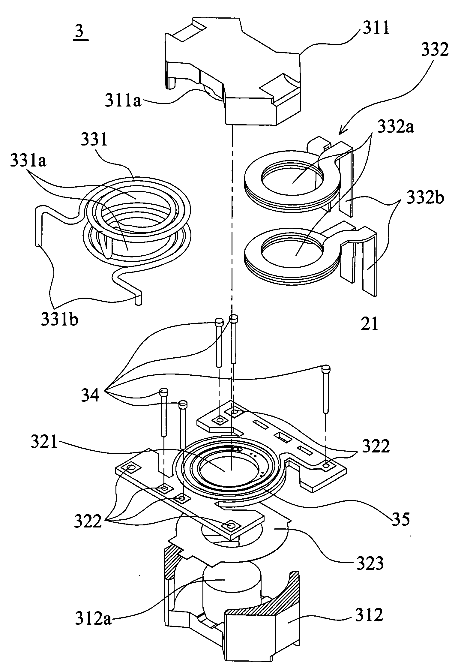
[0020]As shown in FIGS. 3A and 3B, a transformer 3 according to a preferred embodiment of the present invention includes an iron core set 31, a circuit board 32 and a winding assembly 33. The transformer 3 is used in an electronic device.

[0021]The iron core set 31 has a first iron cor...


PUM

PropertyMeasurementUnit
conductionaaaaaaaaaa
sizeaaaaaaaaaa
conductiveaaaaaaaaaa

Abstract

The present invention provides a transformer comprising a core set constructed by a first core and a second core. The first core and second core define a space, a circuit board with at least one hole is disposed in the space; wherein the winding assembly comprises an insulation coil with an extending portion correspondingly passing through the holes and a plurality of conductive pieces are disposed in the insulation coil.

Description

BACKGROUND OF THE INVENTION[0001]1. Field of the Invention[0002]The present invention relates to a transformer satisfying small size and low cost, and in particular, to a transformer conforming to safety standard.[0003]2. Description of the Related Art[0004]The transformer is an electronic component usually used in various electronic equipments. As shown in FIG. 1, the conventional transformer 1 includes a bobbin 11, a winding set 12, a socket mount 14, and an iron core set 13. The winding set 12 includes a primary winding and a secondary winding which are both respectively wound around the bobbin 11 by conductive wires. The primary and secondary windings are electromagnetic coupled to each other. The iron core set 13 consists of a first iron core 131 and a second iron core 132. The first and second iron cores 131, 132 are respectively disposed on the opposite side of the bobbin 11 and coupled together to form an electromagnetic loop.[0005]Generally, the winding set is a winding in ...

Claims


Application Information

Patent Timeline
Patent Type & Authority Applications(United States)
IPC IPC(8): H01F27/30H01F27/28
CPCH01F27/2804H01F27/2828H01F27/2852H01F27/2866H01F27/289H01F2027/297H01F27/306H01F27/324H01F2027/2814H01F2027/2819H01F27/292
Inventor WEI, PO-YU
Owner DELTA ELECTRONICS INC
Why Eureka
Try Eureka