Ultrasonic imaging apparatus and a method of obtaining ultrasonic images

Inactive Publication Date: 2008-04-17
KK TOSHIBA +1
View PDF18 Cites 37 Cited by
  • Summary
  • Abstract
  • Description
  • Claims
  • Application Information

AI Technical Summary

Benefits of technology

[0014]The objective of the present invention is to provide an ultrasonic imaging apparatus, as well as a method of obtaining

Problems solved by technology

However, the image quality of the ultrasonic image obtained by the scan thereby decreases.
However, the volume rate during such a scan will decrease.
Conversely, as the density of the scanning line of ultrasonic beams is lower, the volume rate during the scan improves further, but the image quality of the ultrasonic image obtained by the scan will decrease.
Therefore, it has been impossible to improve the image quality of only the sites that are necessary for diagnosis among the sites represented in an ultrasonic image obtained by a scan.
For example, when obtaining an ultrasonic image of the heart, it has been difficult to improve the image quality of only the heart wall, even while focusing on the heart wall of a heart.
Thus, conventionally, it has been possible to adjust the image quality of the entire

Method used


Image

  • Ultrasonic imaging apparatus and a method of obtaining ultrasonic images
  • Ultrasonic imaging apparatus and a method of obtaining ultrasonic images
  • Ultrasonic imaging apparatus and a method of obtaining ultrasonic images

Examples


modified example 1

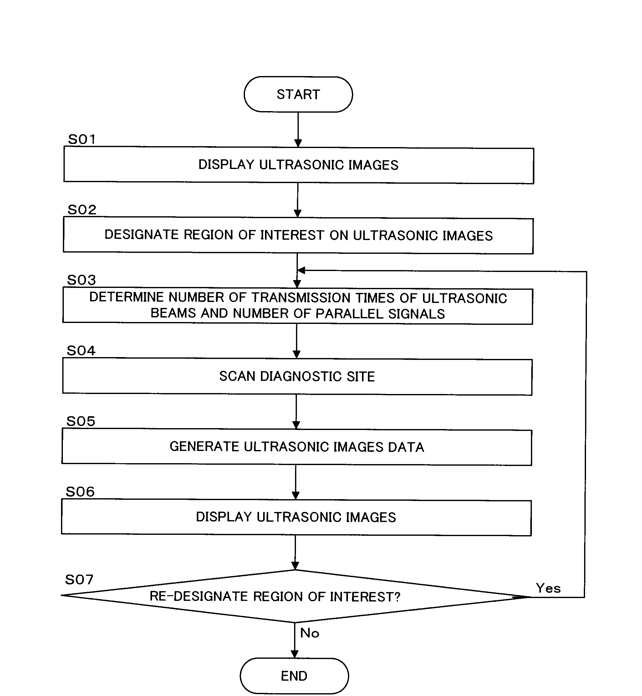
[0095]Next, Modified Example 1 of the abovementioned embodiment will be explained. In the abovementioned embodiment, the transmitter / receiver 3 transmits ultrasonic beams also to regions other than the region of interest (ROI). In this Modified Example 1, the transmitter / receiver 3 may not transmit ultrasonic beams to regions other than the region of interest (ROI). Thus, only the region of interest (ROI) is scanned using ultrasonic beams, so the number of transmission times of ultrasonic beams will be reduced. Consequently, a decrease in the volume rate is prevented, resulting in maintaining real-time properties. At this time, a high-definition image can be obtained by scanning the region of interest (ROI) by raising the scanning line density of the transmission of ultrasonic beams, as is the case with the abovementioned embodiment.

[0096]In addition, in regions to which ultrasonic beams are not transmitted (regions other than the region of interest), the image-generating part 5 gen...

modified example 2

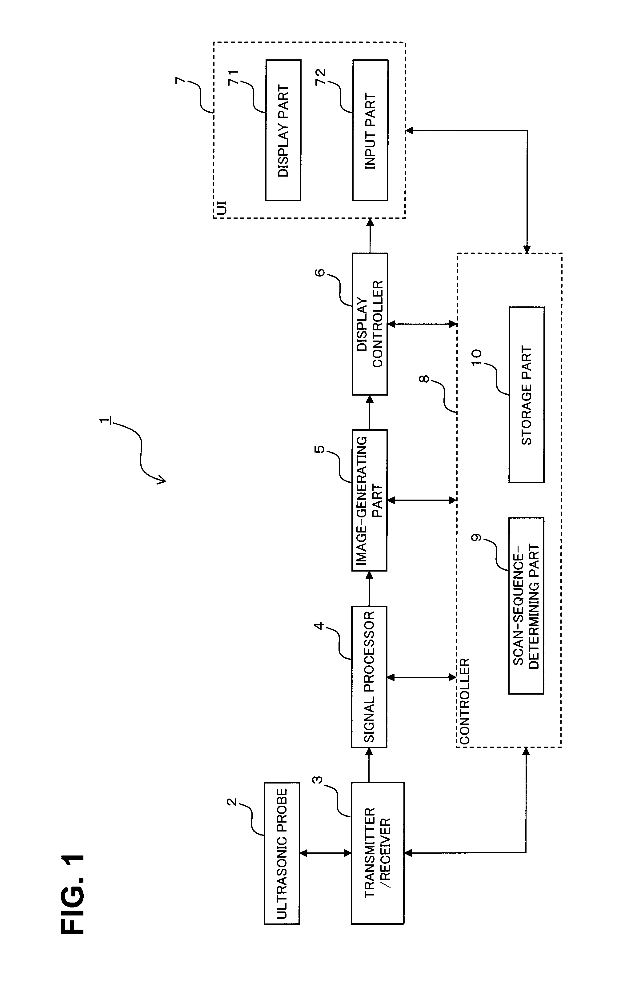
[0097]Next, Modified Example 2 of the abovementioned embodiment will be explained. In Modified Example 2, only a site (e.g., heart wall) that exists in front of the screen is scanned at high resolution in conformity with the orientation of the 3D image that is displayed on the display part 71. The display controller 6 instructs the display part 71 to display the 3D image that has been obtained in advance. When the operator gives an instruction to rotate the 3D image via the input part 72, the display controller 6 then instructs the display part 71 to rotate and display the 3D image in accordance with the instruction for rotation. With a 3D image displayed on the display part 71, rotation-positional information of the 3D image is then outputted from the user interface 7 to the controller 8. The scan-sequence-determining part 9 determines, based on the rotation-positional information, the number of transmission times of ultrasonic beams (scanning line density of the transmission) to t...


PUM


Abstract

An ultrasonic probe and a transmitter/receiver scan a 3D region using ultrasonic beams by raising the scanning line density of the transmission of ultrasonic beams for a region of interest compared to the scanning line density of the transmission of ultrasonic beams for regions other than the region of interest among the 3D regions. An image-generating part generates ultrasonic-image data of the 3D region, based on the received beams that have been obtained by the scan.

Description

BACKGROUND OF THE INVENTION[0001]1. Field of the Invention[0002]The present invention is related to an ultrasonic imaging apparatus and a method of obtaining ultrasonic images for scanning a 3D region using ultrasonic waves. In particular, the present invention is related to an ultrasonic imaging apparatus and the method of obtaining the ultrasonic images for scanning by varying the transmission / reception conditions of ultrasonic waves, depending on the region.[0003]2. Description of the Related Art[0004]An ultrasonic imaging apparatus scans a predetermined range with repeating transmission / reception of ultrasonic waves and generates ultrasonic images, based on data that has been obtained by the scan.[0005]A 2D array probe comprises a plurality of ultrasonic transducers that are two-dimensionally arranged. The 2D array probe can scan a 3D region using ultrasonic beams. Image processing such as volume rendering (hereinafter, may be referred to as “VR processing”) and MPR (Multi-Plana...

Claims


Application Information

Patent Timeline
IPC IPC(8): G06K9/00
CPCA61B8/08
Inventor KURITA, KOICHIRO
Owner KK TOSHIBA
Why Eureka
Try Eureka