Non-ambulatory thermo therapeutic boot for heat and cold therapy of the foot/ankle complex and hand/wrist complex

a non-ambulatory, thermo-therapeutic technology, applied in the field of non-ambulatory thermo-therapeutic boot for heat and cold therapy of the foot/ankle complex and hand/wrist complex, can solve the problems of not being designed for ambulation, weight bearing, or shock absorption, and achieve the effect of convenient storage and convenient preparation for heat or cold therapy

Inactive Publication Date: 2008-04-17
CASELNOVA RONALD J
View PDF10 Cites 4 Cited by
  • Summary
  • Abstract
  • Description
  • Claims
  • Application Information

AI Technical Summary

Benefits of technology

[0036] It is another objective of the present invention to provide one boot device which can be comfortable and worn interchangeably on either the left or right foot / ankle complex.
[0037] It is yet another objective of the present invention to provide two generic sizes that will accommodate the majority of foot sizes that are in need of thermotherapy, without worry or concern for exact sizing to the wearer.
[0038] It is another objective of the present invention to provide a thermotherapy device that will not become hard or brittle when frozen. Because the present invention is a specialized shape, this is of paramount importance.
[0039] It is another objective of the present invention to provide a thermotherapy device for the foot / ankle complex that is easy to store.
[0040] It is a further, an objective of the present invention to provide a thermo therapeutic boot that can be easily prepared for heat or cold therapy in an individual's home freezer, microwave, or boiling water within a reasonable amount of time.
[0041] It is also an objective of the present invention to provide the wearer with a soft, flexible thermotherapy boot that can be comfortably worn for therapy, even in cases of swelling, sub-acute pain and inflammation.

Problems solved by technology

It is not designed for ambulation, weight bearing, or shock absorption.

Method used


Image

  • Non-ambulatory thermo therapeutic boot for heat and cold therapy of the foot/ankle complex and hand/wrist complex
  • Non-ambulatory thermo therapeutic boot for heat and cold therapy of the foot/ankle complex and hand/wrist complex
  • Non-ambulatory thermo therapeutic boot for heat and cold therapy of the foot/ankle complex and hand/wrist complex

Examples


Embodiment Construction

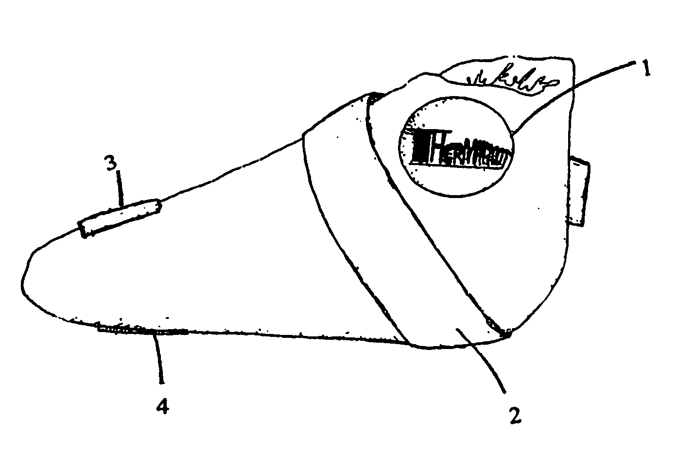
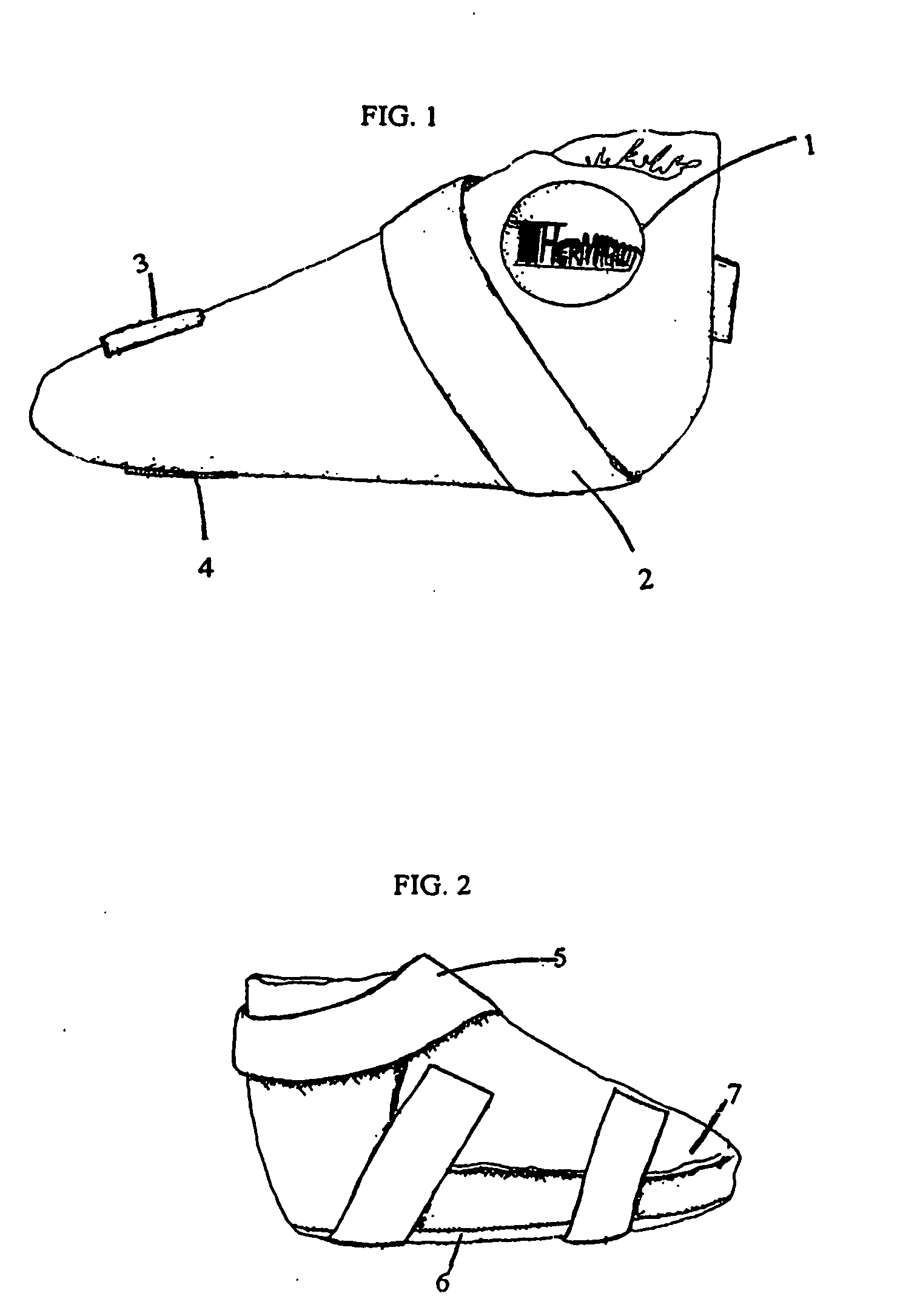
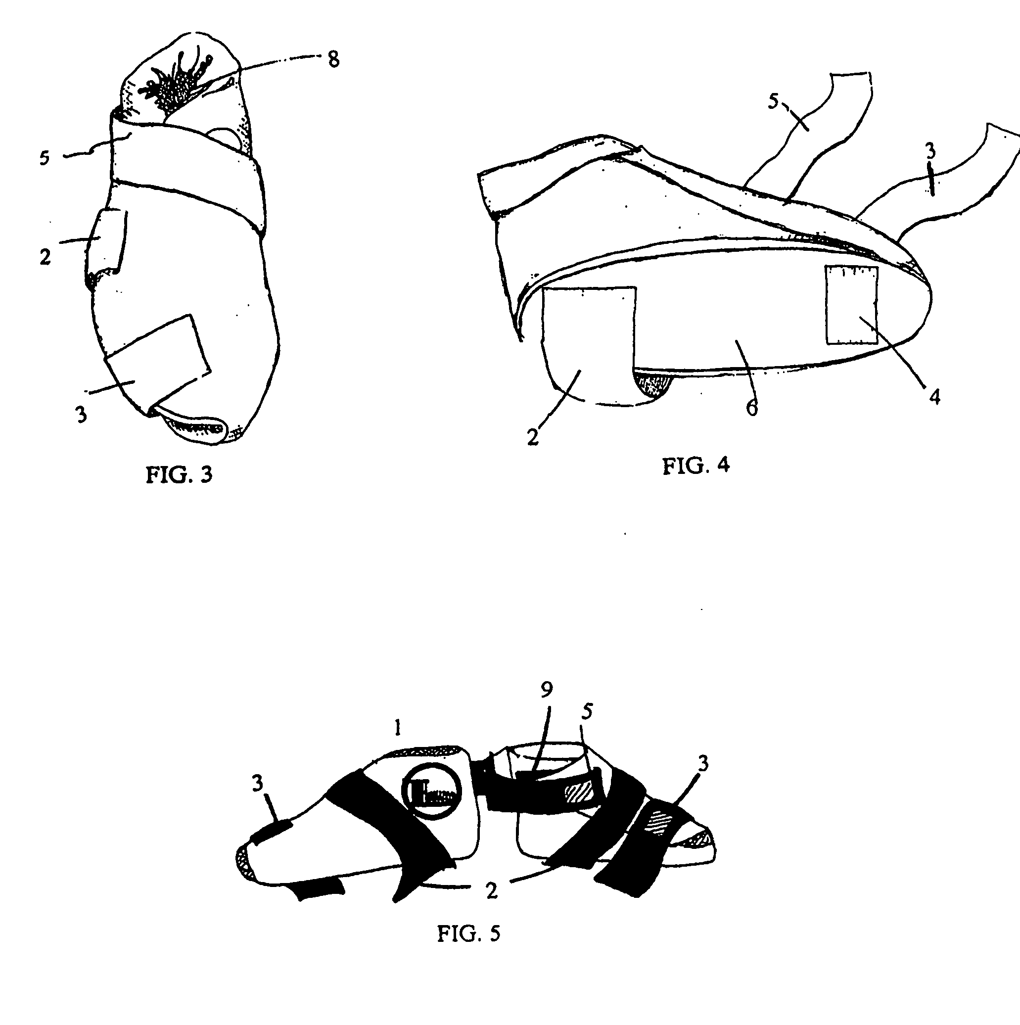
[0066]FIG. 1 shows a sagittal view of the thermotherapy device. The logo label (1) is in plain view. A partial view of fore or mid-foot adjustable strap (2) and the adjustable toe strap (3) are shown. A partial view of the toe strap attachment (4) which is located on the sole of the boot is also shown. The exterior and interior enclosures of the device are made of a high performance textile known as “TEK-STRECH” which has water repellant finish added to it. This allows the boot to be cleaned with a damp cloth or household disinfectant. This textile provides the only enclosure necessary for the solid, soft gel pads.

[0067]FIG. 2 is another sagittal view of Thermaboot™. This illustration shows the ankle strap (5). Also illustrated is a side view of the sole (6) of the device. The sole (6) and body (7) are soft and pliable, which provides not only easy storage, but a comfortable fit for the wearer. This feature of the device is particularly important in cases of discomfort due to infla...


PUM


Abstract

A thermotherapeutic device comprising a thermal pad contains a very thin cloth scrim which is embedded within the shape of the thermal pad for added reinforcement. The thermal pad contains bumps which are disposed throughout the entire interior surface of the pad. The bumps emanate from the thermo-therapeutic solid polymer gel pad, making the technology all one piece. There are a total of two thermal pads, one for the sole and one for the body of the boot called Thermaboot™. The two pads are enclosed within a high performance cloth/textile, and are then sewn together to form the Thermo Therapeutic Boot or a Thermo Therapeutic hand and wrist glove. The intention of the bumps, called Thermabumps™ is to provide a better contact surface between the irregularly shaped contours of the foot and ankle or of the hand and wrist, and the Thermo Therapeutic surface of the boot or glove respectively.

Description

CROSS REFERENCE TO RELATED APPLICATION [0001] This application is a continuation-in-part of application Ser. No. 10 / 438,730 filed May 16, 2003, for A Thermal Pad and Boot Designed for Applying Hot or Cold Treatment which was a continuation-in-part of application Ser. No. 09 / 862,227, filed May 22, 2001 for Therapeutic Boot Having Heat Retaining Protuberances (now abandoned), and provisional application Ser. No. 60 / 207,753, filed May 30, 2001.FIELD OF THE INVENTION [0002] This invention relates to a thermal device comprising a thermal pad and an enclosure containing the thermal pad. The thermal pad consists of solid, pliable gel and bumps disposed throughout the entire surface of the thermal gel pad. One embodiment of the thermal device is a Thermo Therapy Boot comprising two (2) thermal gel pads, one pad for the sole of the boot, and one pad for the body of the boot. When the two pads are sewn in their respective enclosures, the enclosures are then sewn together to form the finished ...

Claims


Application Information

Patent Timeline
Patent Type & Authority Applications(United States)
IPC IPC(8): A61F5/00
CPCA61F7/02A61F2007/101A61F2007/0045A61F2007/0036
Inventor CASELNOVA, RONALD J.
Owner CASELNOVA RONALD J
Why Eureka
Try Eureka