
Assault rifle back-up sight rib and support structure

a technology for supporting structures and assault rifles, applied in the field of sight, can solve the problems of optic sight damage, many m4s carried in the field today are optic sight, and rifles often take quite a beating

Inactive Publication Date: 2008-04-24
KENG
View PDF29 Cites 23 Cited by
  • Summary
  • Abstract
  • Description
  • Claims
  • Application Information

AI Technical Summary

Benefits of technology

[0010] An object of the present invention is to provide a structure and method permitting the user or shooter to continue engaging her or his target after an assault rifle or other weapon carrying an optical sight has been impacted or damaged in a manner that renders an attached optical sight inoperative.
[0011] Another object of the present invention is providing a rugged, low-profile backup sight system that can be brought to bear almost immediately in a natural motion that is easily understood by any user or shooter.

Problems solved by technology

Military arms including assault rifles such as the M16A2 and the M4 are used by soldiers and marines under the most difficult conditions, and those rifles often take quite a beating.
As a result, one problem is that many M4s carried in the field nowadays are optic-sight only.
The rifles carrying the RIS accessory rails are often equipped with either ACOG® AimPoint® or EOTech® optical sights, and optical sights such as these may be damaged when exposed to rough use.
But optical sight removal turns out to be quite a chore in some cases, and the soldier or marine may be engaged in a firefight and unable to stop for a session of impromptu gunsmithing.

Method used


Image

  • Assault rifle back-up sight rib and support structure
  • Assault rifle back-up sight rib and support structure
  • Assault rifle back-up sight rib and support structure

Examples


Embodiment Construction

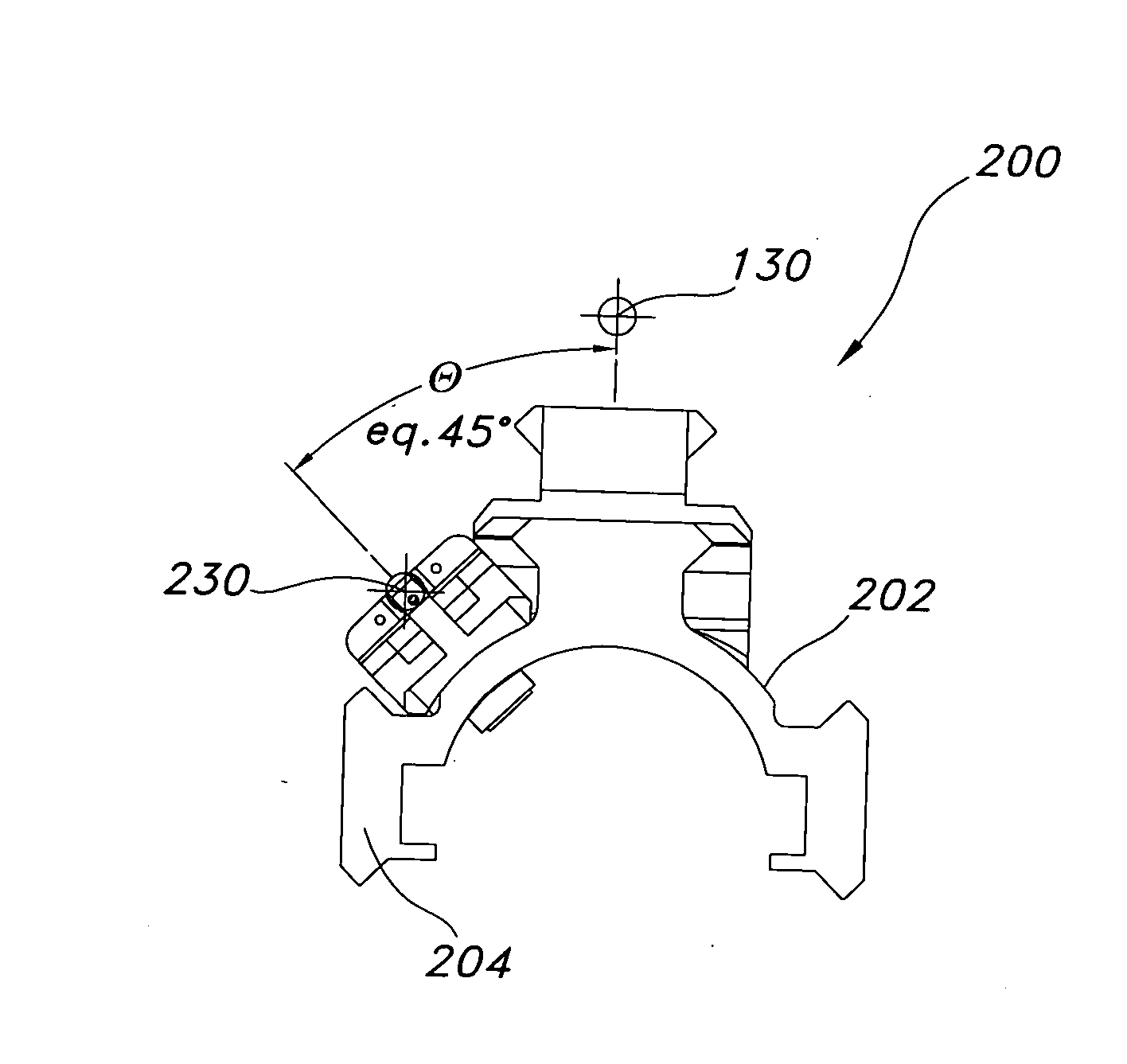
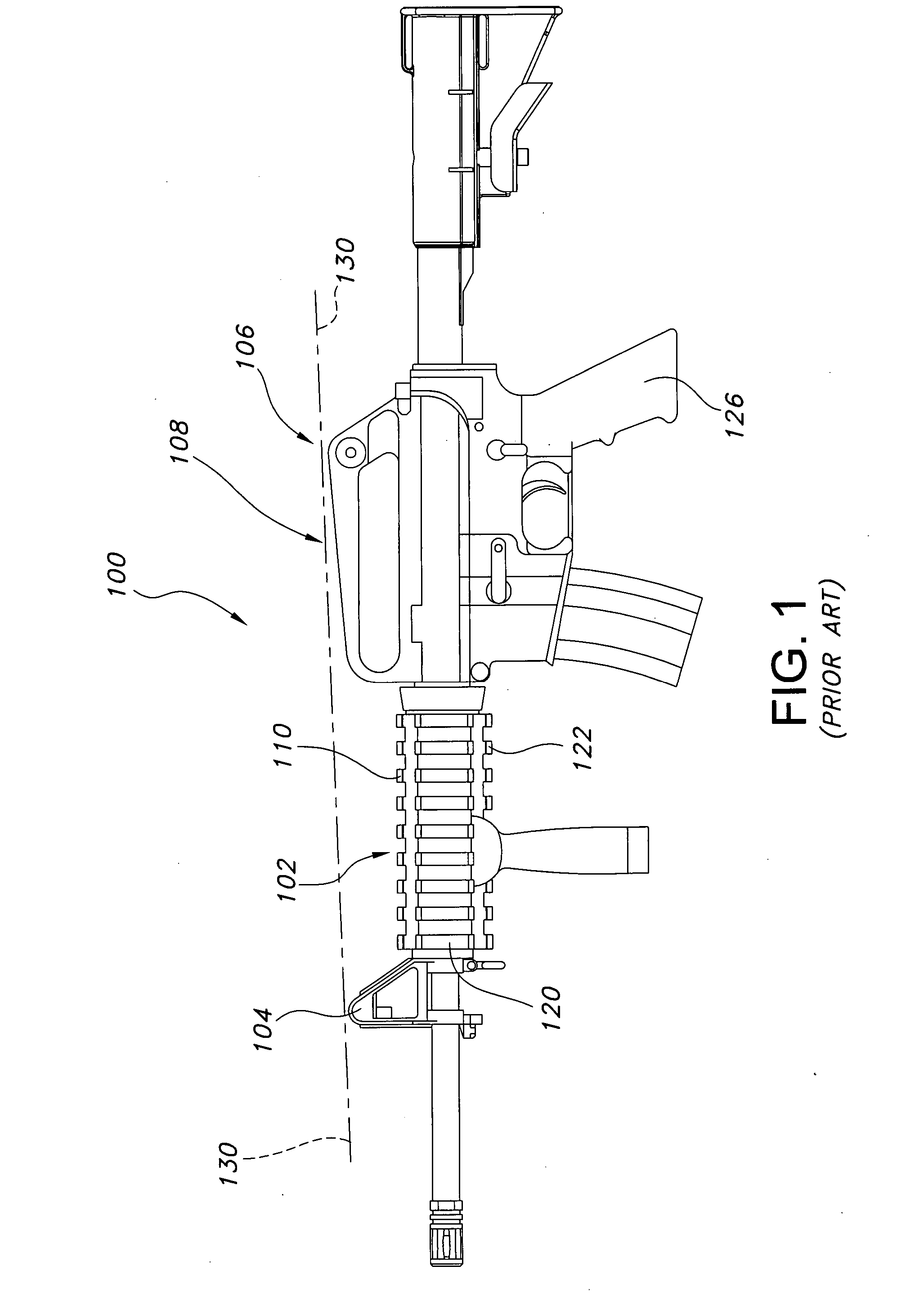
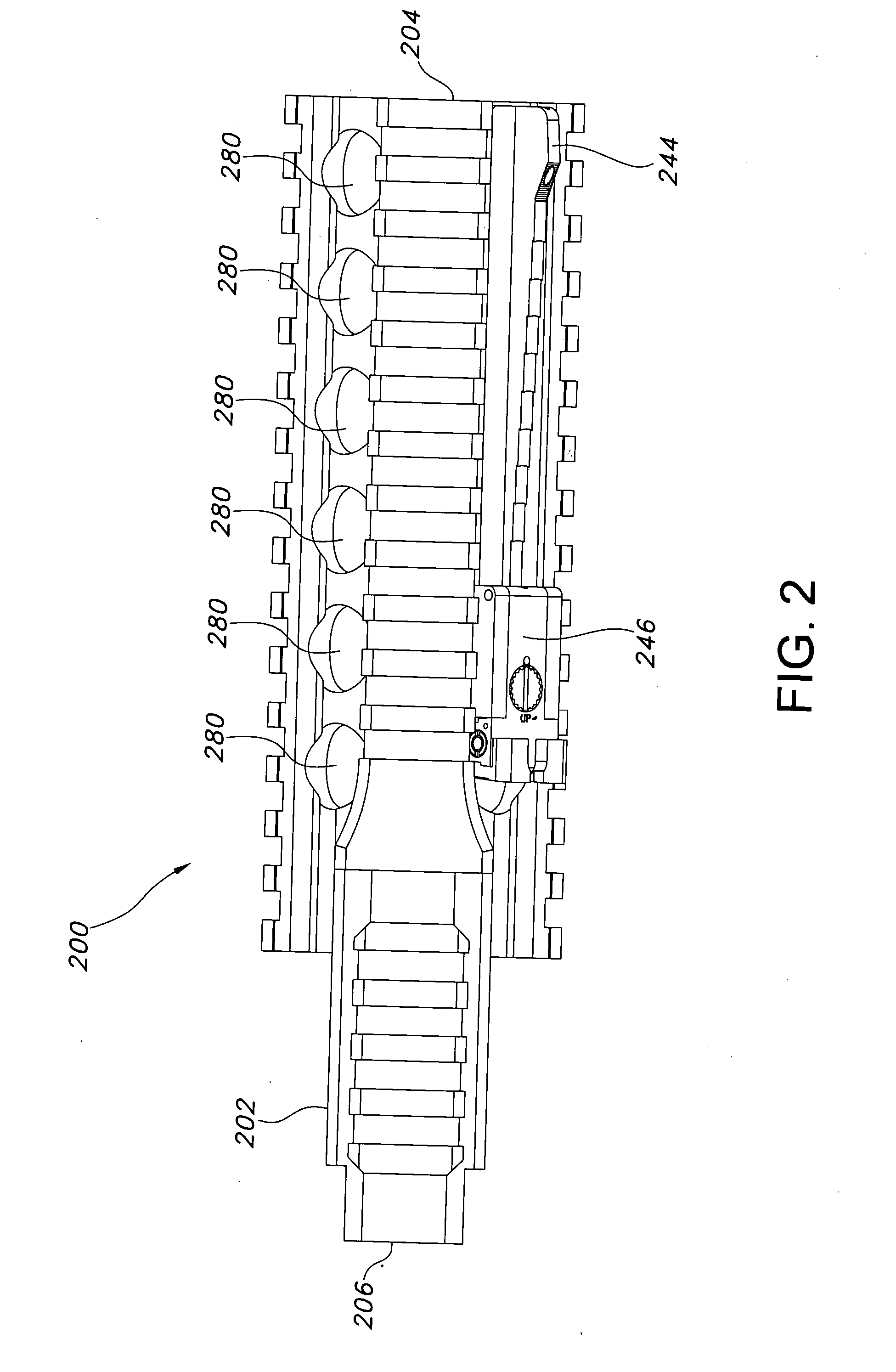
[0029] Referring to FIGS. 1-12, a typical rifle (e.g., an M4) 100 having a Rail Interface System (RIS) fore-end or handguard 102 allows the user to attach a variety of accessories on the RIS rail supports, such as laser pointers, flash lights, bipods. The rifles carrying the RIS accessory rails are often equipped with either ACOG® AimPoint® or EOTech® optical sights (not shown) that may be damaged when exposed to rough use. If a soldier were to drop his or her weapon and that optical sight was rendered ineffective, then the back-up sights typically in use are standard issue front and rear sights 104, 106 that are aligned with the mounting location 108 for the optical sight. Back up iron sights are available on the M4, since the front sight 104 is still affixed to the barrel and rear sight 106 is also provided, but in order to bring the standard back-up iron sights to use, one must remove the damaged optical sight from mounting location 108 and removing the optical sight is easier on...


PUM


Abstract

Back-up sights for use on a rifle configured with an optical sight aligned along a first sighting axis include a handguard or support carrying first and second attachment points that are substantially parallel with the central axis of the rifle's barrel but offset at a different angle than the first sighting axis. A back-up front sight and rear sight are carried on a back-up sight base, where the front sight and rear sight are aligned along a second sight axis that is offset, preferably, by one-eighth turn from the first sighting axis. When using the back-up sights, the user tilts or cants the rifle to one side, rotating the rifle one-eighth turn about the axis of the barrel's bore, to look down the second sighting axis, while aiming the rifle at the target.

Description

[0001] This application claims priority to provisional patent application No. 60 / 748,168, filed Dec. 8, 2005, the entire disclosure of which is incorporated herein by reference.BACKGROUND OF THE INVENTION [0002] 1. Field of the Invention [0003] The present invention relates to sights for use with assault rifles, other military rifles, tactical or hunting firearms or other shooting equipment typically used in exigent circumstances with optical alignment instruments. [0004] 2. Discussion of the Prior Art [0005] Military arms including assault rifles such as the M16A2 and the M4 are used by soldiers and marines under the most difficult conditions, and those rifles often take quite a beating. [0006] The modern soldier or marine can be equipped with a wide variety of equipment and so the rifles have at times been adapted to carry things not formerly found on combat infantry weapons. In response, accessory supporting handguards have been offered that carry from one to four longitudinally ...

Claims


Application Information

Patent Timeline
IPC IPC(8): F41G1/06F41G1/02
CPCF41G11/003F41G1/02
Inventor KENG, DA
Owner KENG
Learn More