Building Methods

a building method and building technology, applied in the direction of structural elements, building components, load-supporting elements, etc., can solve the problems of increasing material and construction costs, adversely affecting the dynamic response of the building, and requiring a corresponding increase in the foundation of the building

Inactive Publication Date: 2008-04-24
ELLEN MURRAY
View PDF15 Cites 4 Cited by
  • Summary
  • Abstract
  • Description
  • Claims
  • Application Information

AI Technical Summary

Benefits of technology

[0027]The structure is preferably a steel portal frame structure, more preferably produced from I or T section beams or from tubular truss assemblies.

Problems solved by technology

The additional material increases material and construction costs and can also adversely affect the building's dynamic response (particularly to earthquakes) and also requires a corresponding increase in the building's foundations.

Method used


Image

  • Building Methods
  • Building Methods
  • Building Methods

Examples


Embodiment Construction

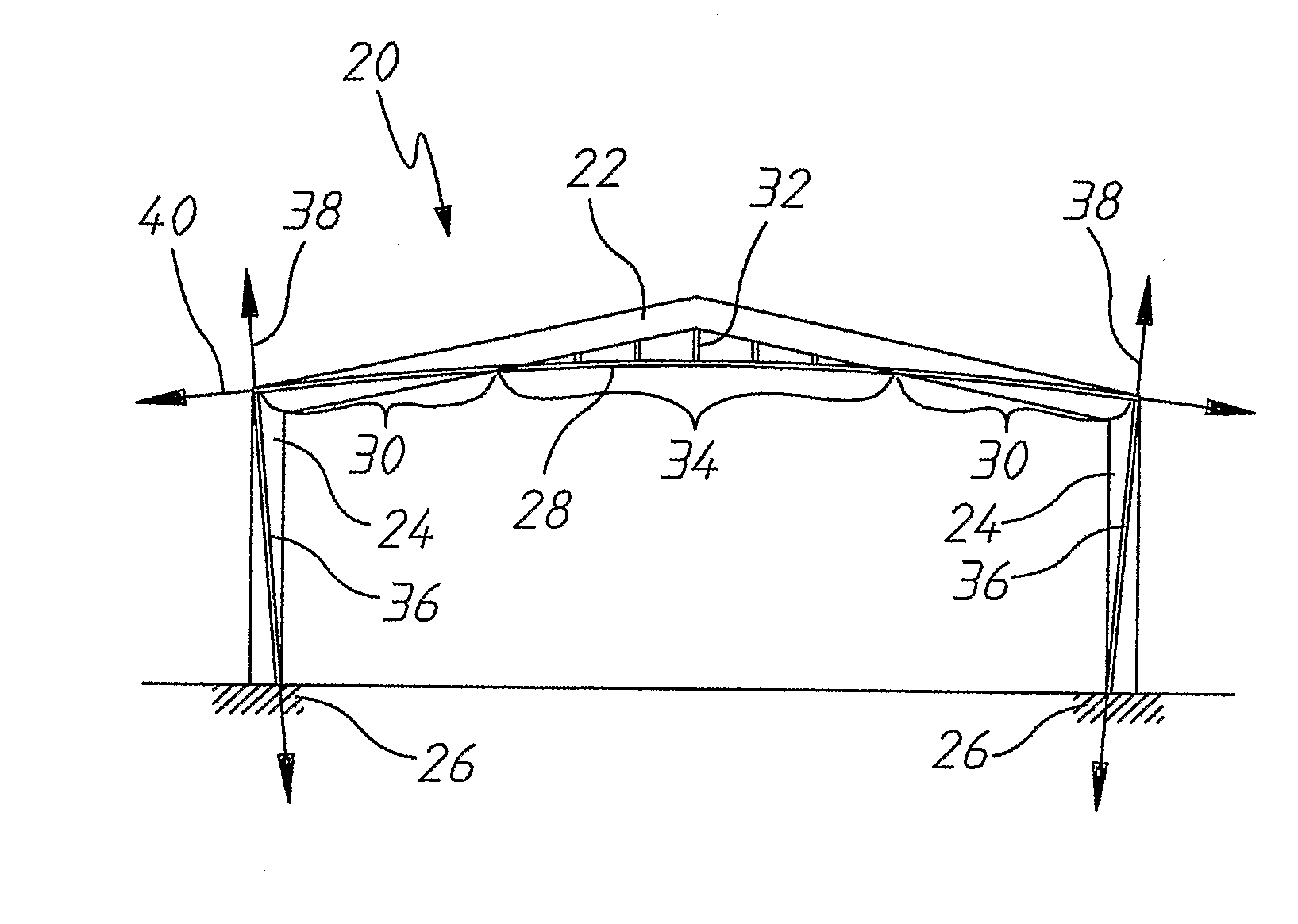
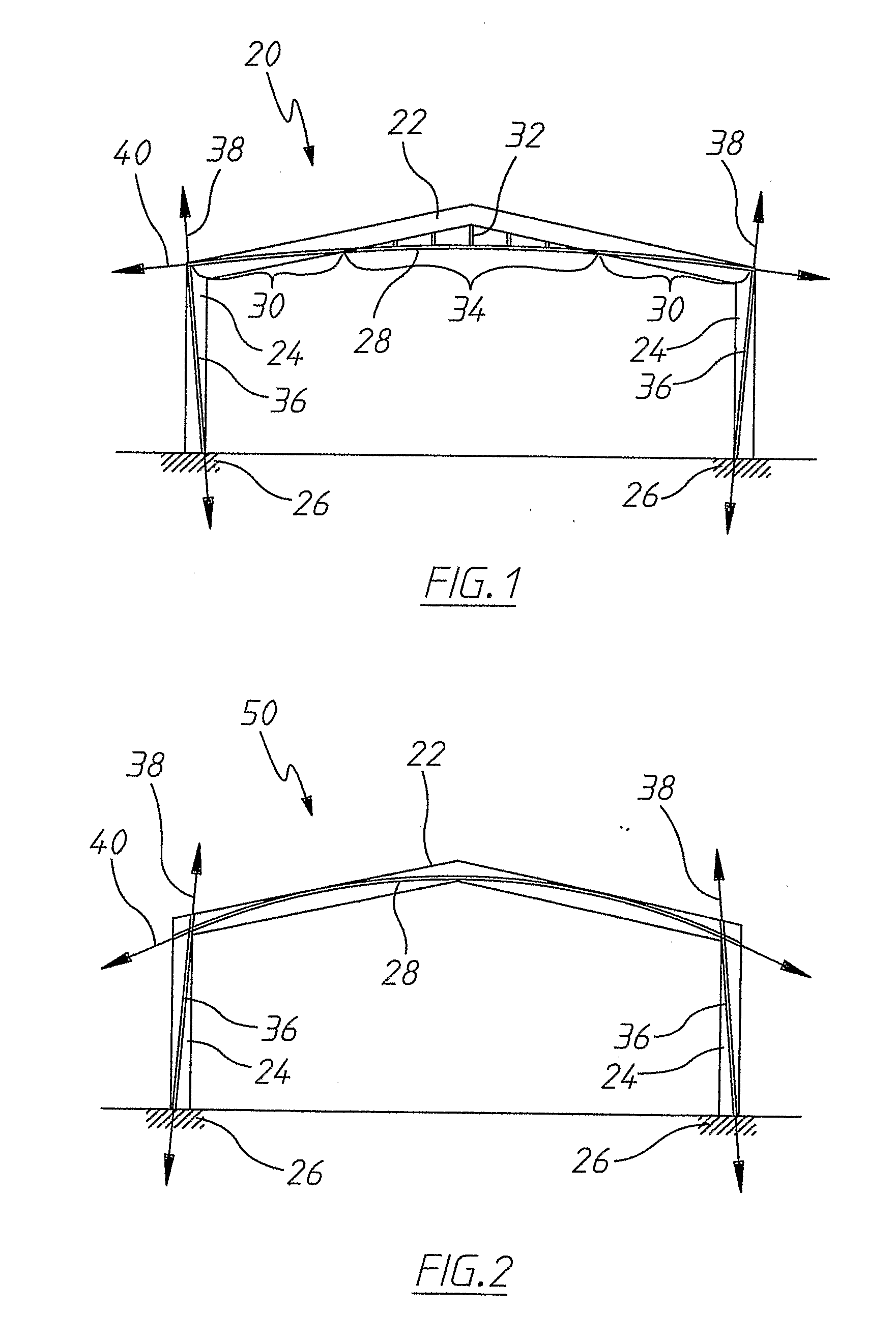
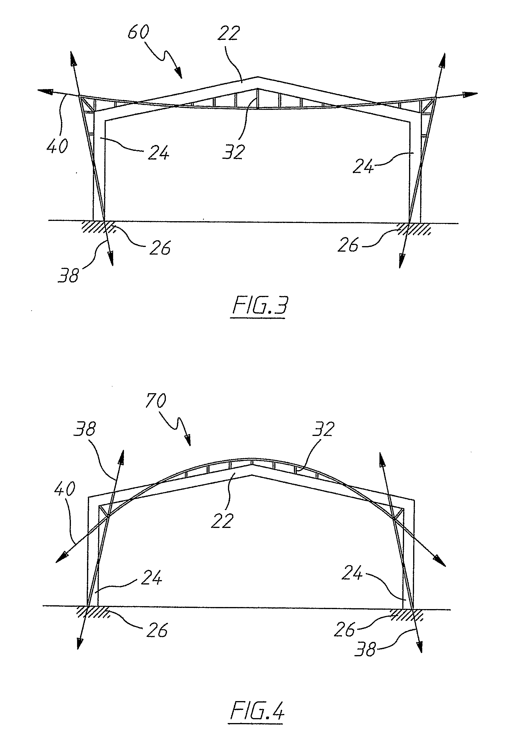
[0038]FIG. 1 shows a (non-steel) portal frame structure 20 formed from a centre span 22, two columns 24 and two foundations 26. Each half of the centre span 22 and each of the columns 24 represent a sub-structure of the steel portal frame structure 20.

[0039]The centre span 22 has a first cable retainer 28 attached thereto, by welding in the regions 30 and via the struts 32 in the region 34. Each of the columns 24 also have cable retainers 36 attached thereto by welding.

[0040]Cables, represented by double headed arrows 38 and 40, are passed through the cable retainers 28 and 36 respectively. The cables 38, 40 are tensioned relative to the cable retainers 28, 36 respectively then bonded to the cable retainers 28, 36 respectively, prior to releasing the tension in the cables. The tensioning, bonding and releasing steps shall be described in more detail below.

[0041]The cable retainers 28, 36 extend generally along the longitudinal direction of their associated centre span (sub-structure...


PUM


Abstract

A method of building a structure, the method including the steps of: 1. fabricating a generally longitudinal, non-steel sub-structure of the structure with a cable retainer attached to, or forming a part of, the substructure and that extends substantially longitudinally therealong; 2. assembling the sub-structure into the structure; 3. inserting a cable into the cable retainer; 4. after step 2, applying a tensile force to the cable relative to the cable retainer; and 5. after step 4, bonding the cable to the cable retainer.

Description

FIELD OF THE INVENTION[0001]The present invention relates to a method of building a structure and also to a method to strengthening, or reducing the deflection of, a built structure.[0002]The invention has been primarily developed for use in relation to portal frame structures that use materials other than steel, such as: aluminium and other alloys; carbon fibre; plastics; ceramics; timber; or glass and will be described hereinafter with reference to these applications. However, the invention is not limited to this field of use and is also applicable for other non-steel structural and architectural works.BACKGROUND OF THE INVENTION[0003]When designing a structure or building, consideration must be given to, amongst others requirements, the requirements of strength, deflection and dynamics. It is common for additional material to be required in a structure to satisfy deflection requirements, when compared to the material required to satisfy strength requirements. The additional mater...

Claims


Application Information

Patent Timeline
Patent Type & Authority Applications(United States)
IPC IPC(8): E04B1/00
CPCE04B1/24E04B1/26E04B1/28E04B2001/2487E04B2001/3583E04C5/08E04C3/292E04C3/38E04C3/40E04C3/42E04C3/10E04B1/35E04C3/02E04C3/18E04C3/26
Inventor ELLEN, MURRAY
Owner ELLEN MURRAY
Why Eureka
Try Eureka