Coded Linear Magnet Arrays in Two Dimensions

a linear magnet array and coded technology, applied in the field of field emission system and method, to achieve the effect of improving and extending the operation of existing magnetic field devices

Inactive Publication Date: 2009-10-08
CORRELATED MAGNETICS RES LLC
View PDF19 Cites 71 Cited by
  • Summary
  • Abstract
  • Description
  • Claims
  • Application Information

AI Technical Summary

Benefits of technology

[0005]Therefore there is a need for new magnetic field configurations providing new magnetic field properties that can improve and extend the operation of existing ...

Problems solved by technology

Moreover, commercial, consumer, and industrial products and fabrication processes abound with a myriad of fasteners, latches, hinges, pivots, bearings and other devices that are conventionally ba...

Method used


Image

  • Coded Linear Magnet Arrays in Two Dimensions
  • Coded Linear Magnet Arrays in Two Dimensions
  • Coded Linear Magnet Arrays in Two Dimensions

Examples


Embodiment Construction

[0044]The present invention will now be described in detail, but first, a brief description of magnets and coded magnet structures will be given to clarify the notation and terminology of this disclosure.

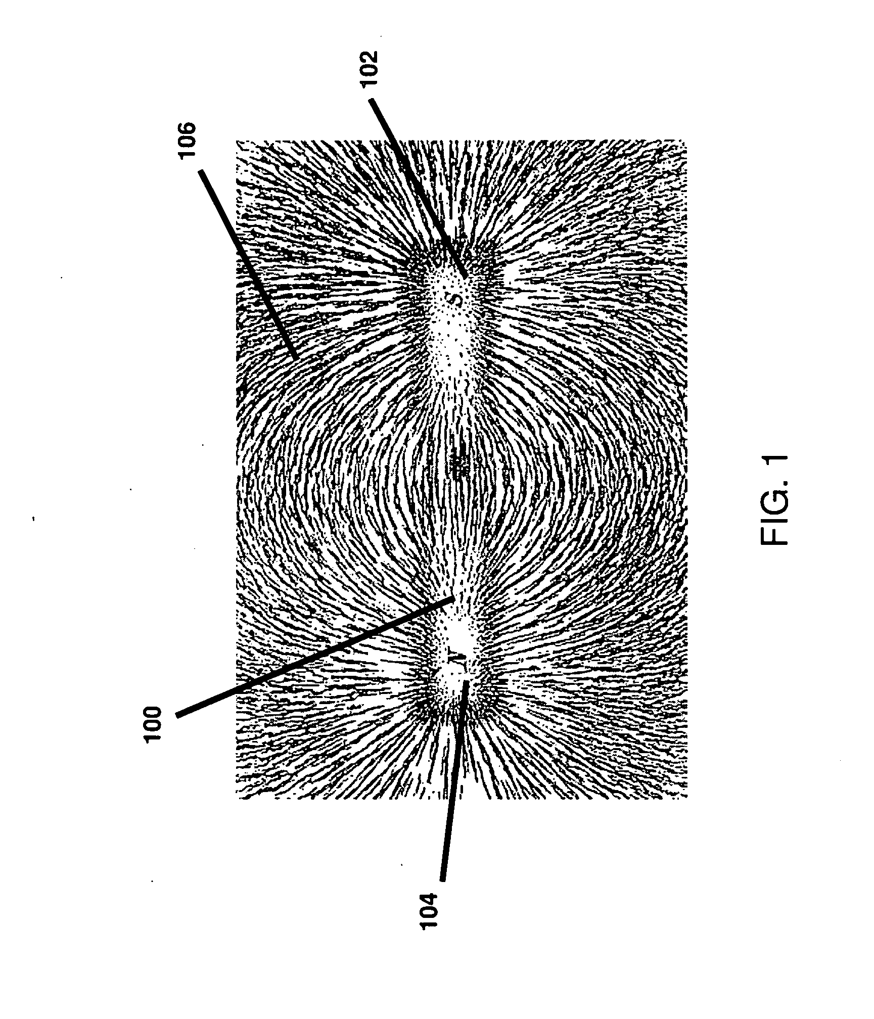
[0045]FIG. 1 depicts iron filings oriented in the magnetic field (i.e., field domain) produced by a single bar magnet. Referring to FIG. 1, a magnet 100 has a South pole 102 and a North pole 104. The iron filings 106 tend to orient in the direction of magnetic field vectors that represent the direction and magnitude of the magnet's moment. North and South poles are also referred to herein as positive (+) and negative (−) poles, respectively. In accordance with the invention, magnets can be permanent magnets, impermanent magnets, electromagnets, involve hard or soft material, and can be superconductive. In some applications, magnets can be replaced by electrets.

Coded Magnet Structures

[0046]Coded magnet structures were first fully disclosed in U.S. Provisional Patent Application 61 / ...


PUM


Abstract

Field emission structures comprising electric or magnetic field sources having magnitudes, polarities, and positions corresponding to a desired spatial force function where a spatial force is created based upon the relative alignment of the field emission structures The magnetic field sources may be arranged according to a code having a desired autocorrelation function. In particular, a high peak to sidelobe autocorrelation performance may be found desirable. Specific exemplary embodiments are described having non-parallel linear substructures. The non-parallel linear substructures may use the same or different codes and may have none, one, or more magnets in common. Other embodiments include substructures spaced according to a spacing code. Exemplary spacing codes include, but are not limited to Golomb ruler or Costas array. A polarity code may be applied across the substructures.

Description

RELATED APPLICATIONS[0001]This Non-provisional application is a continuation-in-part of Non-provisional application Ser. No. 12 / 476,952 filed Jun. 2, 2009, by Fullerton et al., titled “A Field Emission System and Method”, which is a continuation-in-part of Non-provisional application Ser. No. 12 / 322,561, filed Feb. 4, 2009 by Fullerton et al., titled “System and Method for Producing an Electric Pulse”, which is a continuation-in-part application of Non-provisional application Ser. No. 12 / 358,423, filed Jan. 23, 2009 by Fullerton et al., titled “A Field Emission System and Method”, which is a continuation-in-part application of Non-provisional application Ser. No. 12 / 123,718, filed May 20, 2008 by Fullerton et al., titled “A Field Emission System and Method”, which claims the benefit under 35 USC 119(e) of U.S. Provisional Application Ser. No. 61 / 123,019, filed Apr. 4, 2008 by Fullerton, titled “A Field Emission System and Method”. The applications listed above are incorporated by re...

Claims


Application Information

Patent Timeline
IPC IPC(8): H01F7/00
CPCH01F7/0284
Inventor FULLERTON, LARRY W.ROBERTS, MARK D.RICHARDS, JAMES LEE
Owner CORRELATED MAGNETICS RES LLC
Why Eureka
Try Eureka