Land rig

a technology of land rigs and rigging wheels, which is applied in earthwork drilling, metal working equipment, cranes, etc., can solve the problems of unstable masts and relatively long masts, and achieve the effect of facilitating operations

Inactive Publication Date: 2009-01-01
VARCO I P INC
View PDF32 Cites 71 Cited by
  • Summary
  • Abstract
  • Description
  • Claims
  • Application Information

AI Technical Summary

Benefits of technology

[0012]In certain aspects, the present invention provides a land rig for erecting a mast and raising a substructure in which main lines need not be unhooked and reposition...

Problems solved by technology

With such a system the mast assembly can be relatively long...

Method used


Image

  • Land rig
  • Land rig
  • Land rig

Examples


Embodiment Construction

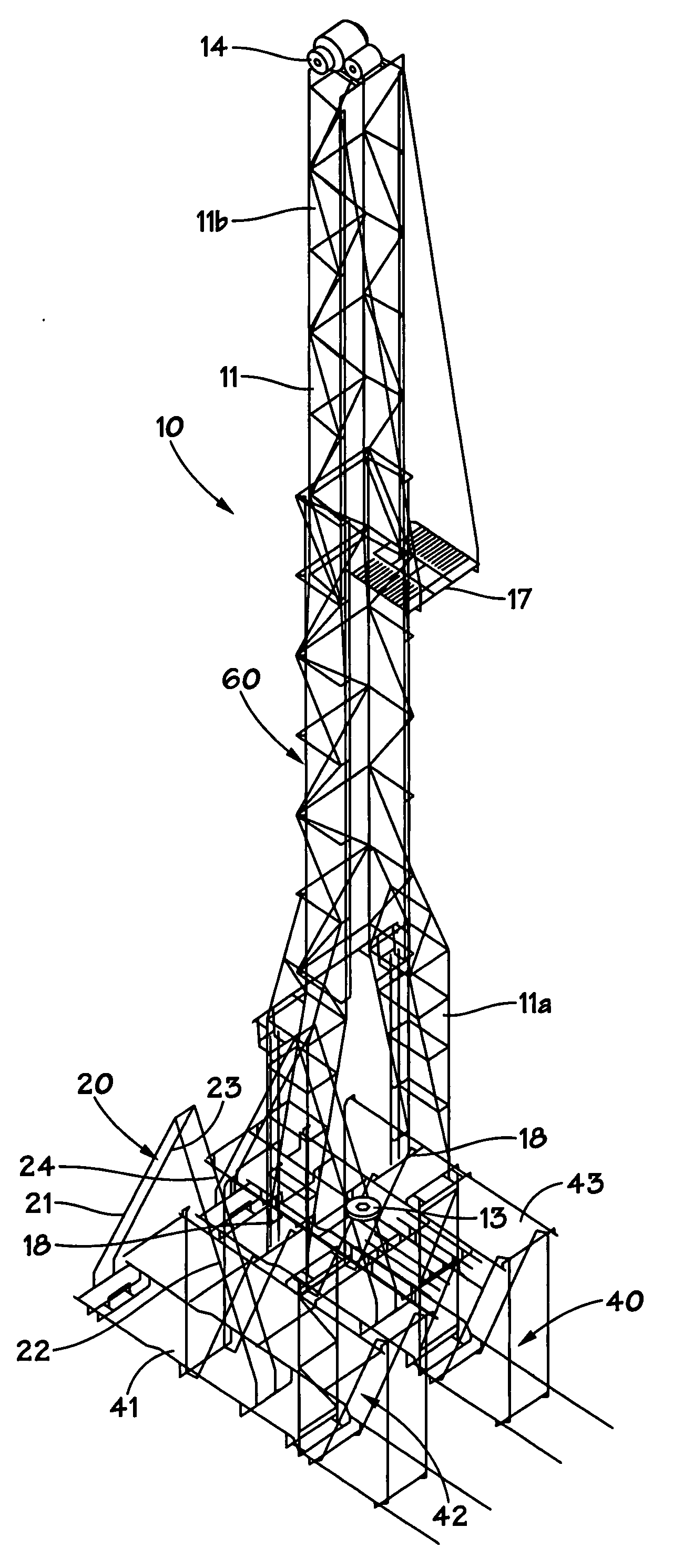
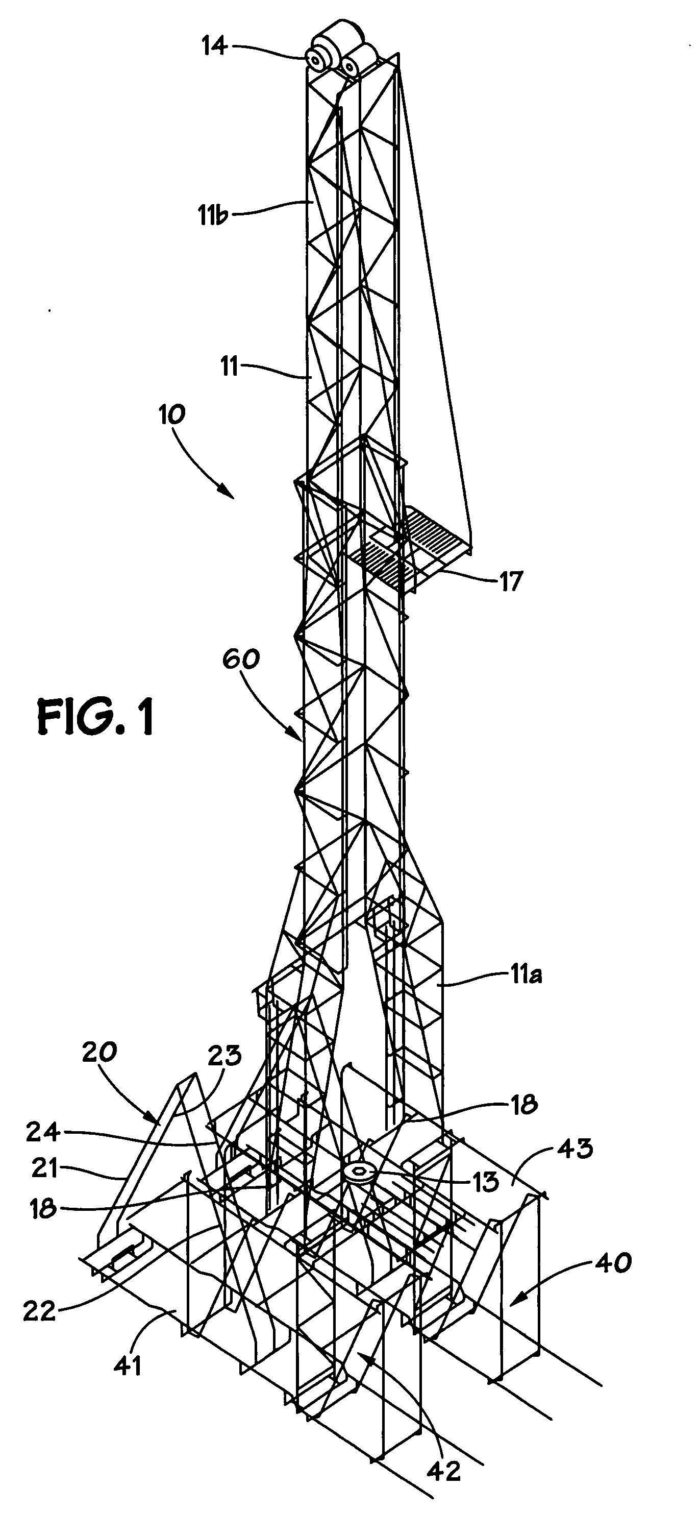
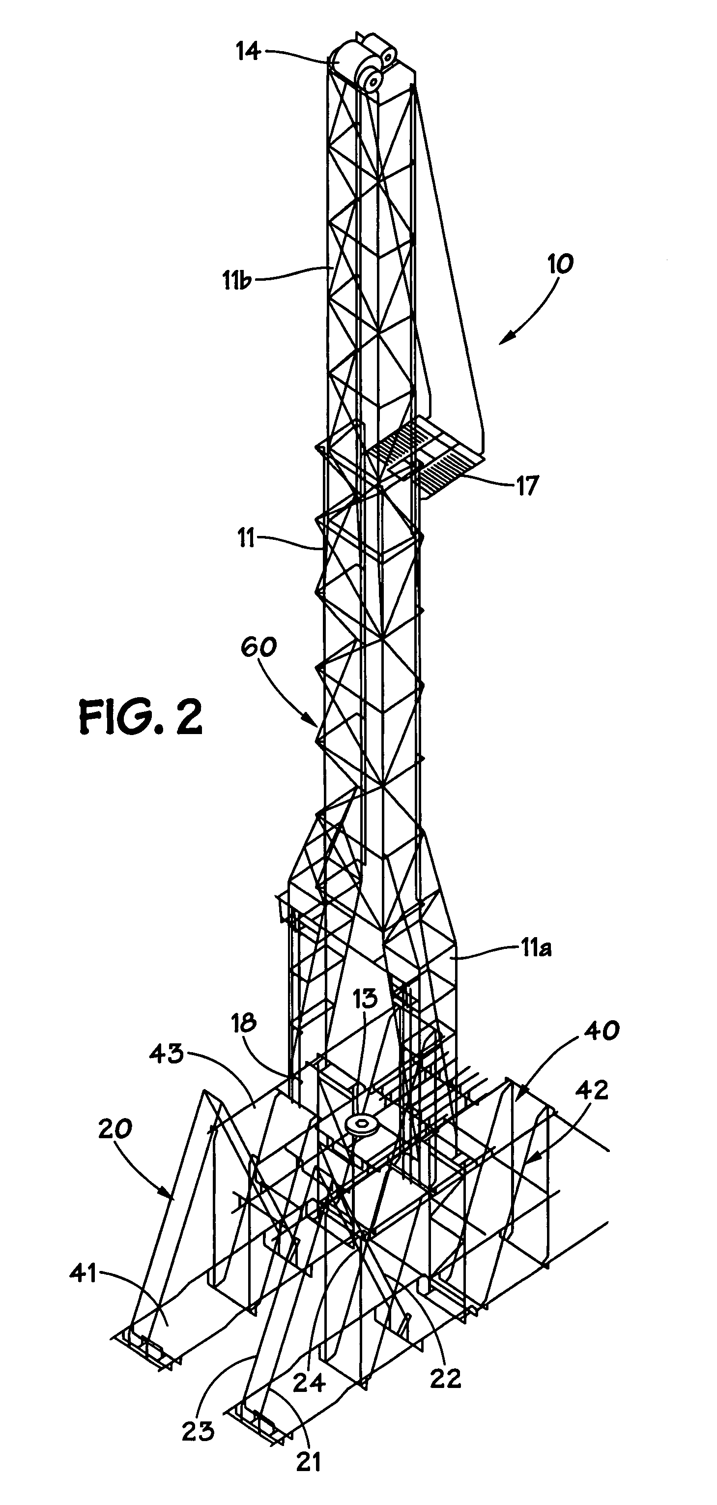
[0044]FIGS. 1, 2 and 3 show a land rig 10 according to the present invention which includes an A-frame apparatus 20 mounted on a substructure 40 and a mast system 60 (with a mast 11) movable from a generally horizontal position (as shown, e.g. in FIGS. 3 and 5A) to an erect, upright position (as shown, e.g. in FIGS. 5D, 5E).

[0045]The land rig 10 may include any and all the typical associated equipment, controls, hoists, drawworks, apparatuses, devices and systems used with any known land rig. As shown the land rig 10 includes tubular rotation apparatus (e.g. a top drive system 12 and / or a rotary apparatus 13) on the mast 11; a crown sheave or block 14; a travelling block 15 (see FIG. 3); a raising sheave 16; an optional racking board 17; mast ends 18, two of which, 18a, pivot on a top part 43 of a substructure 40 and two of which, 18b, are selectively connectible to the top part 43; and a drawworks system 19.

[0046]The mast 11 may be any suitable known mast (single-piece, multi-piece...


PUM


Abstract

A land rig including a mast, a substructure beneath the mast, the substructure having a top part, movement apparatus connected to the substructure, the movement apparatus connected to the mast, the movement apparatus for moving the mast and for moving the top part of the substructure. This abstract is provided to comply with the rules requiring an abstract which will allow a searcher or other reader to quickly ascertain the subject matter of the technical disclosure. It is submitted with the understanding that it will not be used to interpret or limit the scope or meaning of the claims, 37 CFR 1.72(b).

Description

BACKGROUND OF THE INVENTION[0001]1. Field of the Invention[0002]This invention is directed to land rigs; such rigs for wellbore drilling; such rigs with an erectable mast and / or substructure portion; and methods of their use.[0003]2. Description of Related Art[0004]The prior art discloses a variety of rigs used in drilling and various wellbore operations; for example, and not by way of limitation, U.S. Pat. Nos. 3,340,938; 3,807,109; 3,922,825; 3,942,593; 4,269,395; 4,290,495; 4,368,602; 4,489,526; 4,569,168; 4,837,992; 6,634,436; 6,523,319 and the references cited in these patents—all these patents incorporated fully herein for all purposes.[0005]In many land drilling operations, land rigs are delivered to a site, assembled and then disassembled. It is important that land rig components be easily transported and assembled. Costs associated with land rigs and associated equipment, can be calculated on a per hour or per day basis, and, therefore, efficient takedown, transport, and se...

Claims


Application Information

Patent Timeline
IPC IPC(8): E04H12/18
CPCE21B15/00
Inventor LEE, DOUGLAS WAYNEMCCOO, MARCUS SHERWIN
Owner VARCO I P INC
Why Eureka
Try Eureka