Exhaust purification device of engine

a technology of exhaust purification device and engine, which is applied in the direction of engine components, machines/engines, mechanical equipment, etc., can solve the problems of inability to add reducing agent to the exhaust passage upstream of the catalyst, freezing of reducing agent in the reducing agent passage,

Inactive Publication Date: 2008-04-24
DENSO CORP
View PDF11 Cites 71 Cited by
  • Summary
  • Abstract
  • Description
  • Claims
  • Application Information

AI Technical Summary

Benefits of technology

[0010]It is an object of the present invention to provide an exhaust purification device of an engine capable of thawing a reducing agent in a frozen state promptly so that the reducing agent can be used in an early stage without causing increase of load applied to a power source due to power consumption.

Problems solved by technology

If air temperature falls at night or the like in a cold district, there is a possibility that the reducing agent in the reducing agent passage freezes.
Due to the freeze, the addition of the reducing agent to the exhaust passage upstream of the catalyst becomes impossible.

Method used


Image

  • Exhaust purification device of engine
  • Exhaust purification device of engine
  • Exhaust purification device of engine

Examples


Embodiment Construction

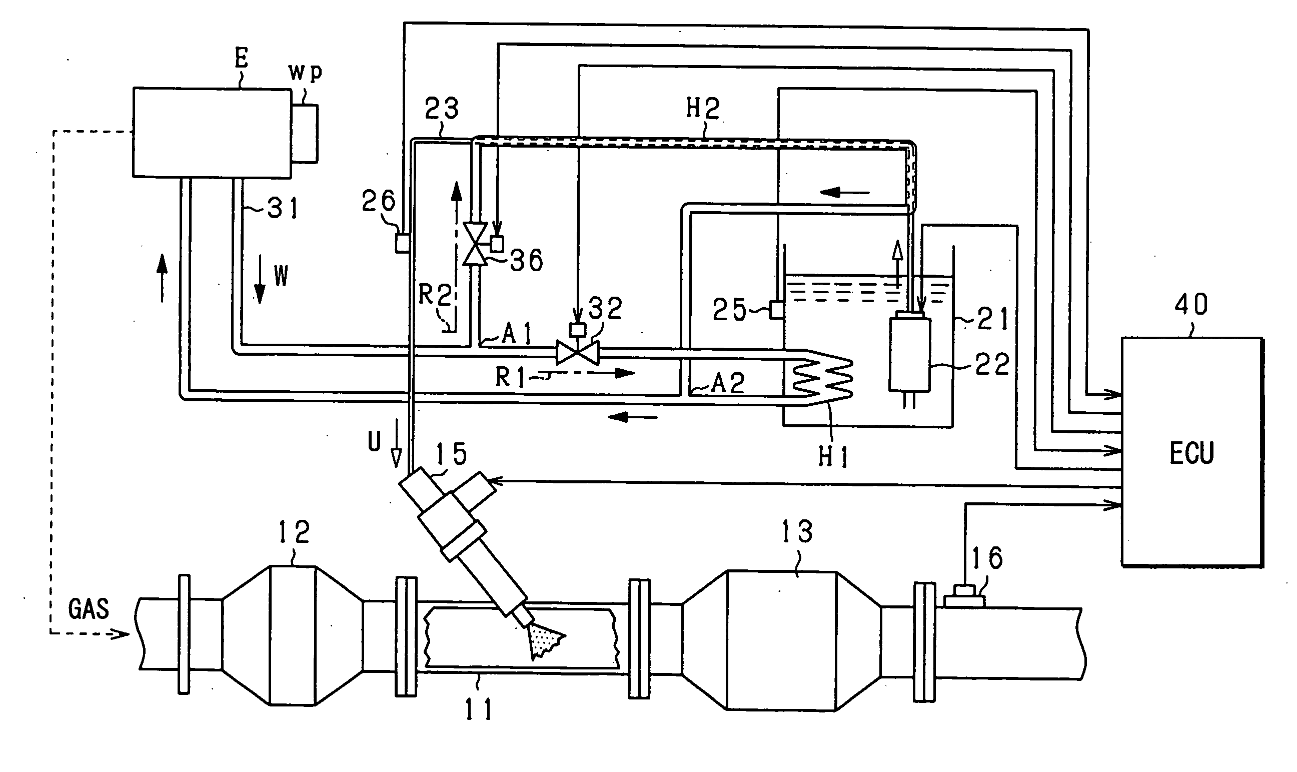
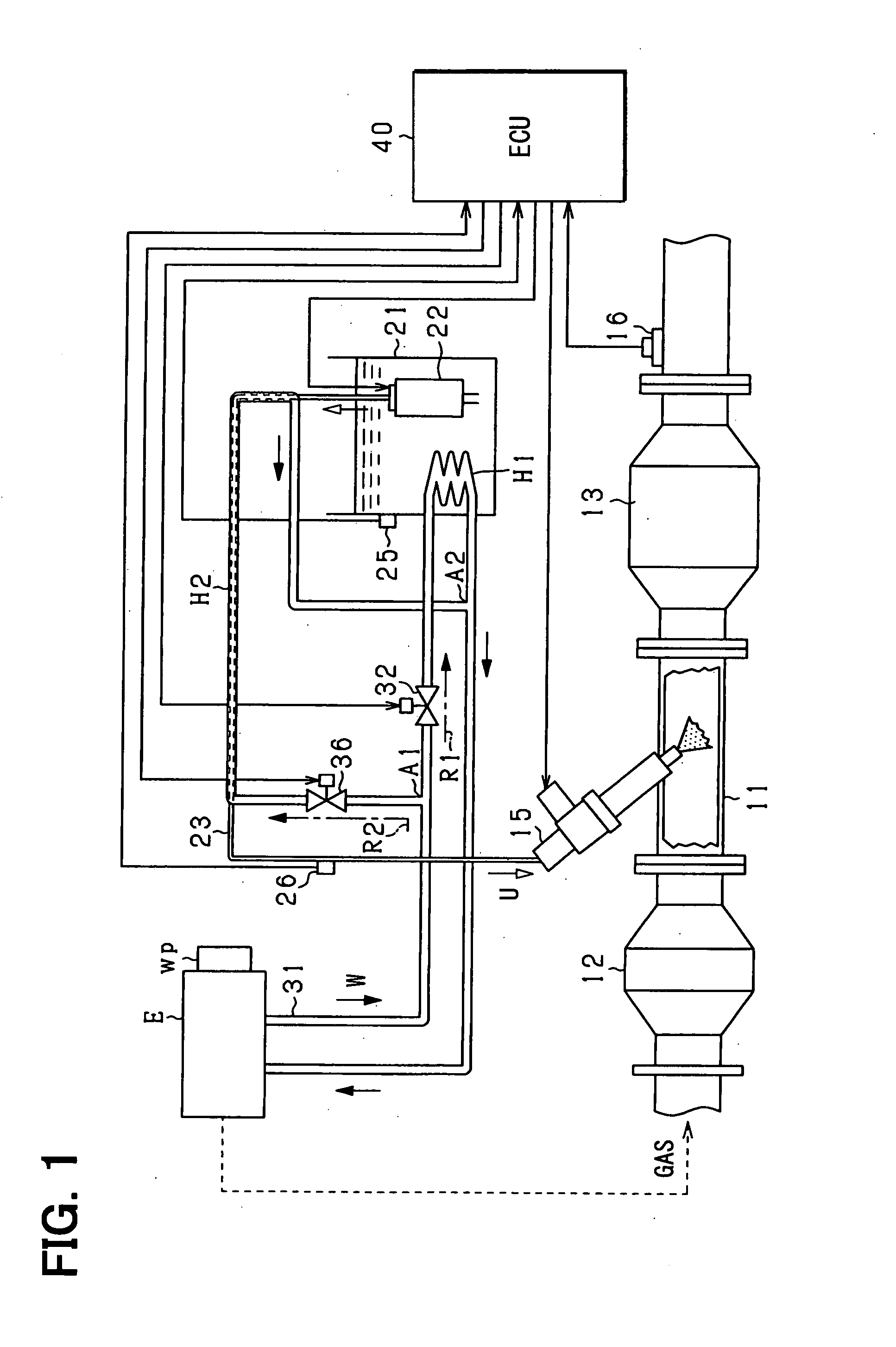
[0022]Now, an exhaust purification device according to an embodiment of the present invention will be explained in reference to drawings. The exhaust purification device according to the present embodiment purifies NOx in exhaust gas using a selective reduction catalyst and is structured as a urea SCR system. First, the structure of the system will be explained in detail with reference to FIG. 1. FIG. 1 is a schematic diagram showing the urea SCR system according to the present embodiment. The present system purifies exhaust gas discharged by a diesel engine (not shown) mounted in a vehicle. As shown in FIG. 1, the system mainly has various actuators, various sensors, an ECU 40 (electronic control unit) and the like for purifying the exhaust gas.

[0023]As a structure of engine exhaust system, an exhaust pipe 11 connected to an engine main body E is provided. A DPF 12 (diesel particulate filter) and a selective reduction catalyst 13 (SCR catalyst) are provided in the exhaust pipe 11. ...


PUM


Abstract

A DPF and a SCR catalyst are provided in an exhaust pipe, and a urea solution addition valve is provided between the DPF and the SCR catalyst for performing addition supply of urea solution into the exhaust pipe. In a urea solution supply system, the urea solution of prescribed concentration is stored in a urea solution tank, and a urea solution pump is provided in the tank. A urea solution supply pipe is connected to the urea solution pump. A part of the urea solution supply pipe is structured as a compound pipe structure defining two passages. One of the two passages serves as a urea solution passage, and the other one serves as an engine coolant passage.

Description

CROSS REFERENCE TO RELATED APPLICATION[0001]This application is based on and incorporates herein by reference Japanese Patent Application No. 2006-284628 filed on Oct. 19, 2006.BACKGROUND OF THE INVENTION[0002]1. Field of the Invention[0003]The present invention relates to an exhaust purification device of an engine, and more specifically to an exhaust purification device suitably applicable to a urea SCR (Selective Catalytic Reduction) system.[0004]2. Description of Related Art[0005]In recent years, a urea SCR system has been developed and has been partly put into practical use as an exhaust purification device for purifying NOx (nitrogen oxides) in exhaust gas at a high purifying rate in an engine (specifically, diesel engine) applied to a vehicle or the like. A following structure is known as a urea SCR system.[0006]That is, in the urea SCR system, a SCR catalyst is provided in an exhaust pipe connected to an engine main body, and a urea solution addition valve for adding urea so...

Claims


Application Information

Patent Timeline
Patent Type & Authority Applications(United States)
IPC IPC(8): F01N3/10
CPCF01N3/0821F01N3/2066F01N2610/02F01N13/009F01N2610/14F01N2610/1486Y02T10/24F01N2610/10Y02T10/12
Inventor SUZUKI, KAZUNORIKUROYANAGI, MASATOSHINISHIJIMA, YOSHIAKI
Owner DENSO CORP
Why Eureka
Try Eureka