Exhaust gas purification system having particulate filter

a technology of exhaust gas purification system and particulate filter, which is applied in the direction of machines/engines, electrical control, separation processes, etc., can solve the problems of increased pressure loss in the dpf, difficulty in calculating the precise pm trapped quantity, and deficiency such as the lowering of engine outpu

Inactive Publication Date: 2004-05-18
DENSO CORP
View PDF7 Cites 62 Cited by
  • Summary
  • Abstract
  • Description
  • Claims
  • Application Information

AI Technical Summary

Problems solved by technology

If a quantity of the trapped particulate matters increases, pressure loss in the DPF increases and deficiency such as lowering of engine output may occur.
Thus, it is difficult to calculate the precise PM trapped quantity only from the pressure difference between the upstream and the downstream of the DPF.
However, even in this scheme, the effect of the variation in the state of the SOF cannot be eliminated fully.
If the PM trapped quantity is calculated to be smaller than an actual quantity, excessive particulate matters may be trapped and excessive heat may be generated by a rapid burning of the particulate matters when the DPF is regenerated.
Accordingly, a possibility of damage to the DPF caused by excessive heat generation may increase as the PM trapped quantity M increases.
As a result, fuel consumption of the engine may increase, or a quantity of the fuel provided to the burner or power consumption by the heater may increase.

Method used


Image

  • Exhaust gas purification system having particulate filter
  • Exhaust gas purification system having particulate filter
  • Exhaust gas purification system having particulate filter

Examples


first embodiment

(First Embodiment)

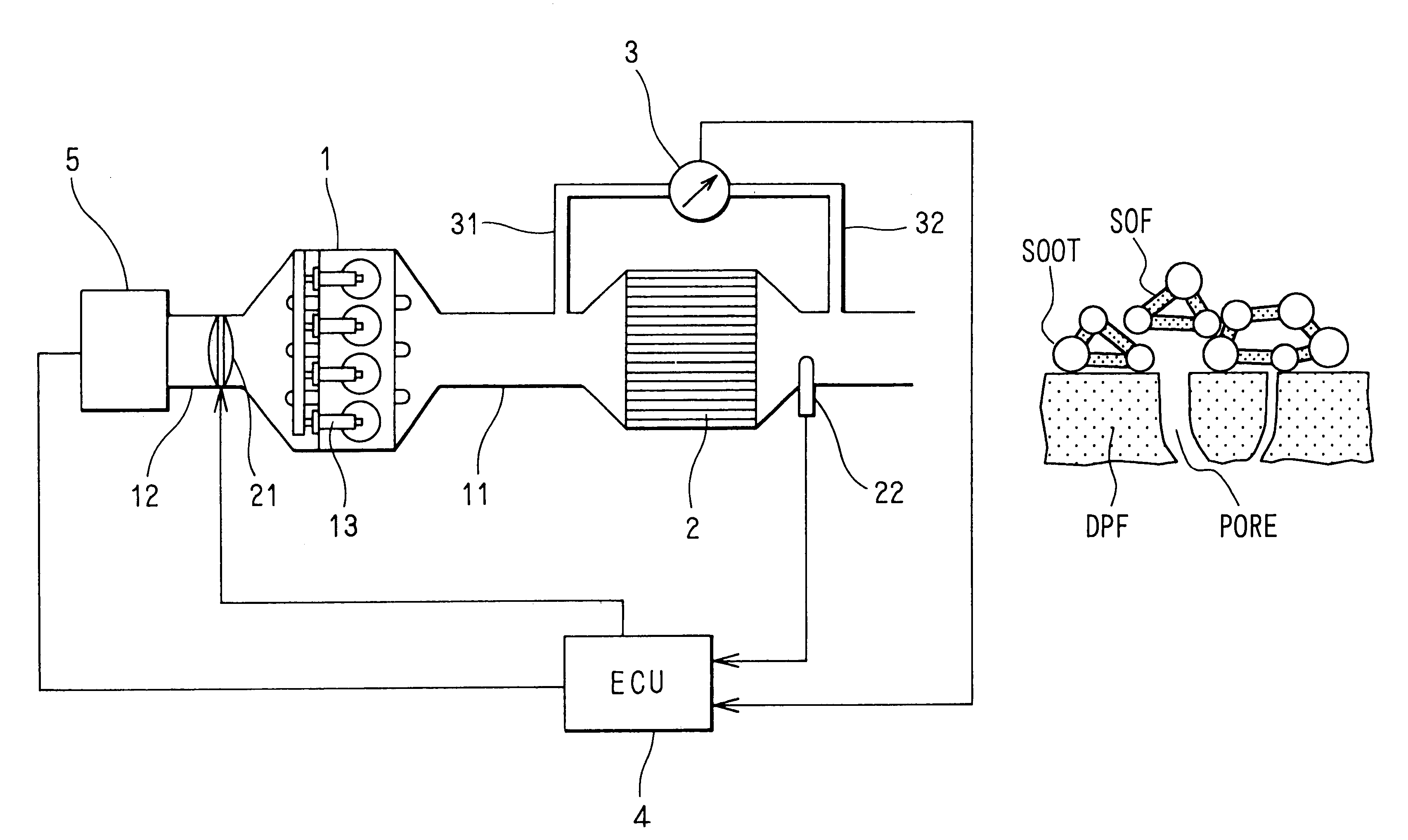
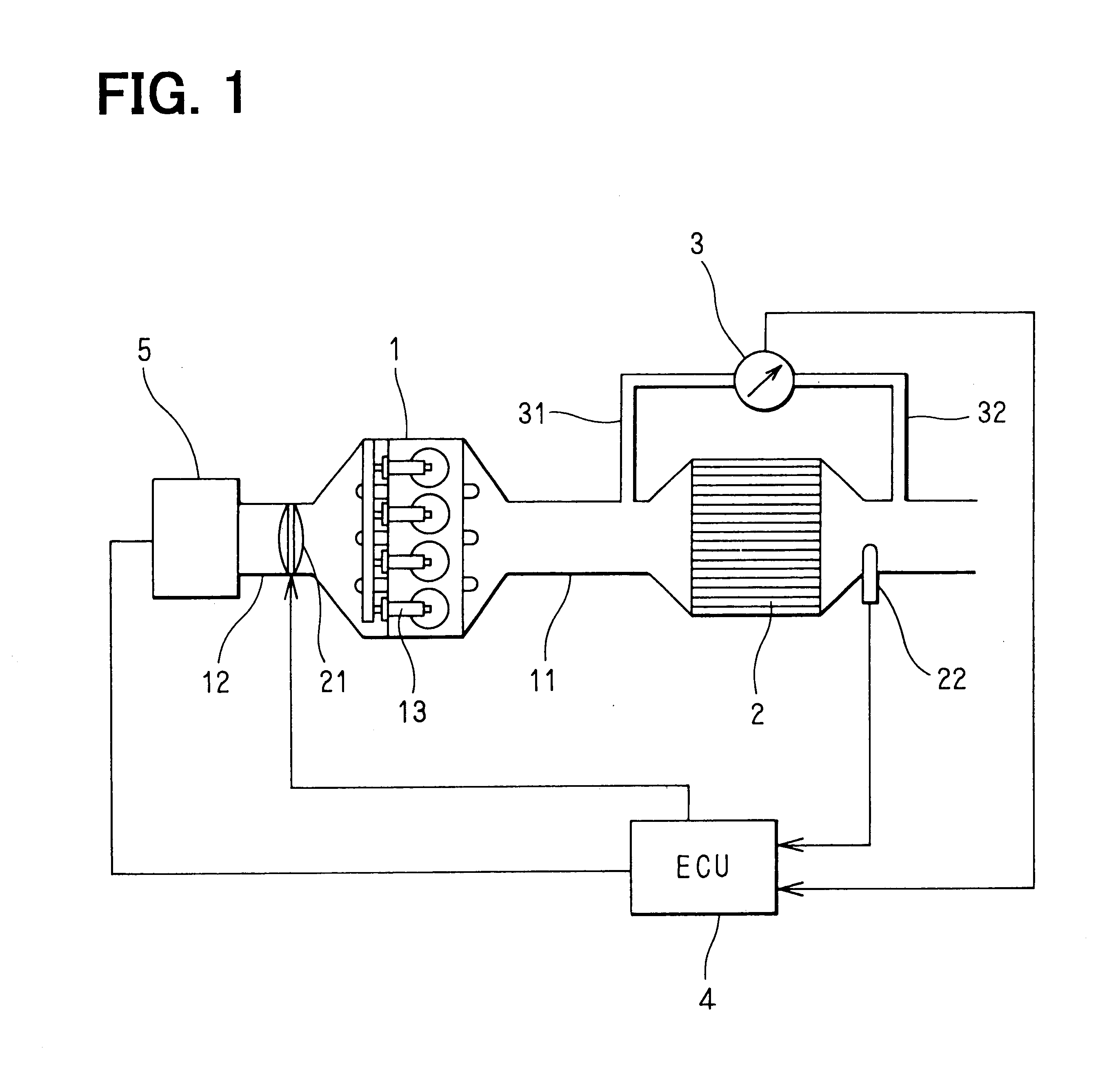
Referring to FIG. 1, an exhaust gas purification system of a diesel engine 1 is illustrated. A diesel particulate filter (DPF) 2 is disposed in an exhaust pipe 11 of the engine 1. The DPF 2 has a publicly known structure. The DPF 2 is made of heat-resistant ceramics such as cordierite and is formed in the shape of a honeycomb. The honeycomb has a matrix of porous filter walls forming a multiplicity of cells extending from one end to another end of the honeycomb. An inlet side end or an outlet side end of each cell is blocked alternately. The exhaust gas discharged from the engine 1 enters the cells whose inlet side ends are open. When the exhaust gas passes through the porous filter wall, particulate matters (PM) are trapped.

A pressure difference measuring device 3 such as a plurality of pressure sensors is disposed in order to measure a quantity of the particulate matters trapped by the DPF 2 (PM trapped quantity). Pressure in the exhaust pipe 11 in the upstream o...

second embodiment

(Second Embodiment)

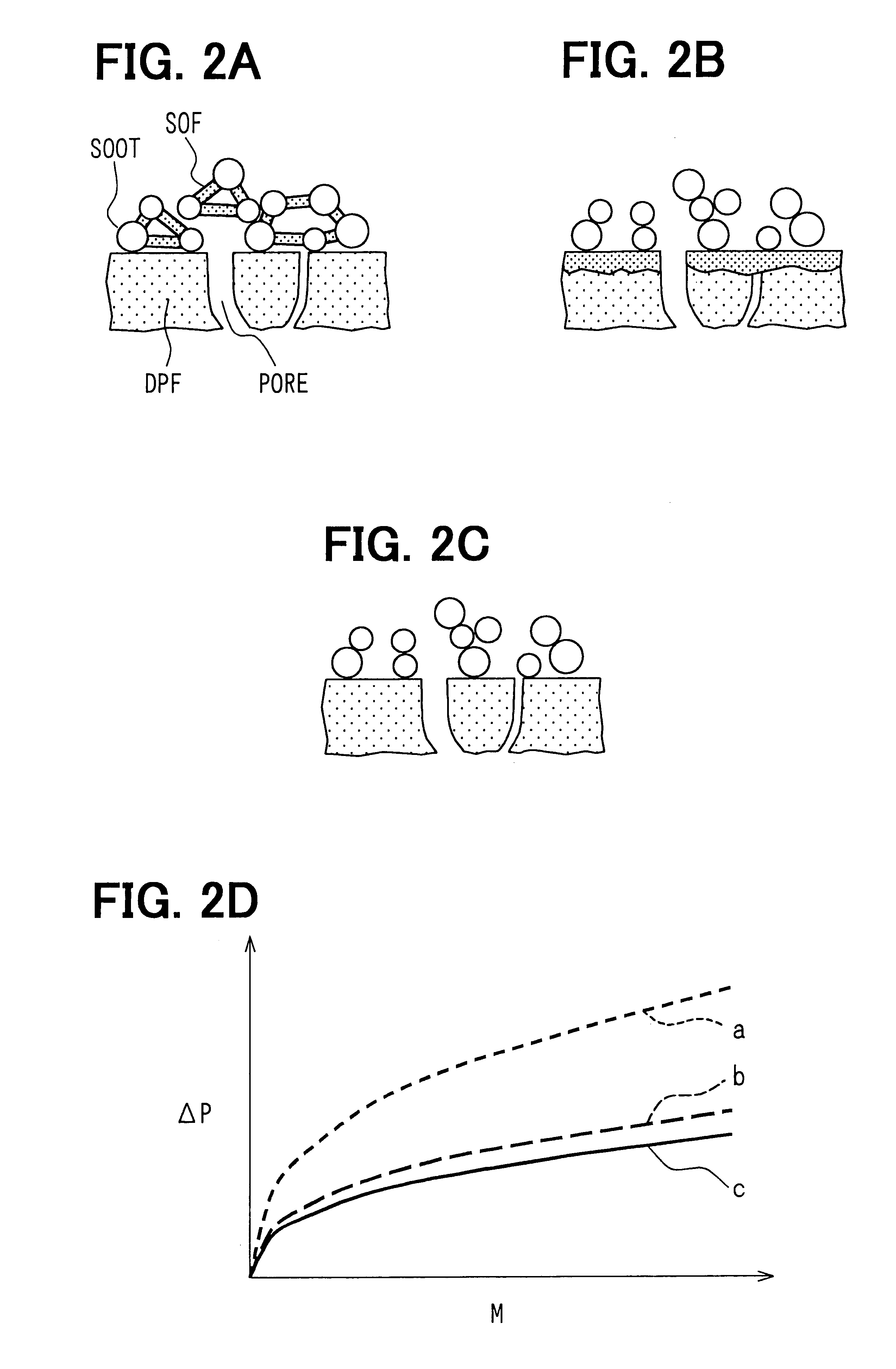
A regeneration control method of the exhaust gas purification system according to the second embodiment will be explained based on FIGS. 6 and 7. In the exhaust gas purification system, after the DPF 2 is heated to the temperature at which the SOF can be eliminated by the gasification or the oxidization, the PM trapped quantity is calculated based on the pressure difference between the upstream and the downstream of the DPF 2 and the exhaust gas flow rate. The exhaust gas flow rate is calculated from the measured values of the DPF temperature and the intake airflow rate. Meanwhile, change of the PM trapped quantity with time is calculated. If the change of the PM trapped quantity with time becomes equal to or less than a predetermined value, the SOF is determined to be substantially eliminated. The PM trapped quantity at that time is measured. When the measured PM trapped quantity becomes equal to or larger than a predetermined quantity, the DPF 2 is regenerated b...


PUM

PropertyMeasurementUnit
temperatureaaaaaaaaaa

Abstract

An engine control unit of an exhaust gas purification system of an internal combustion engine measures a pressure difference between an upstream and a downstream of a diesel particulate filter (DPF) after heating the DPF at least to a predetermined temperature and maintaining the DPF at the temperature for a while. The DPF is disposed in an exhaust pipe of the engine. A soluble organic fraction included in particulate matters in exhaust gas can be eliminated at the predetermined temperature. The ECU calculates a quantity of the particulate matters trapped by the DPF from the measured pressure difference. Thus, the quantity of the trapped particulate matters is calculated precisely, independently of a composition of the particulate matters or a state of the soluble organic fraction.

Description

This application is based on and incorporates herein by reference Japanese Patent Application No. 2002-123867 filed on Apr. 25, 2002.1. Field of the InventionThe present invention relates to an exhaust gas purification system that has a particulate filter for trapping particulate matters included in exhaust gas discharged from an internal combustion engine. Specifically, the present invention relates to an exhaust gas purification system capable of precisely measuring a quantity of the trapped particulate matters.2. Description of Related ArtVarious devices for reducing particulate matters discharged from diesel engines are proposed as measures for protecting the environment. A typical example of such devices is a diesel particulate filter (DPF) disposed in an exhaust pipe. The DPF adsorbs and traps the particulate matters included in exhaust gas when the exhaust gas passes through porous filter walls of the DPF. The surface of the filer wall may be coated with an exhaust gas purifi...

Claims


Application Information

Patent Timeline
Patent Type & Authority Patents(United States)
IPC IPC(8): F02D41/02F01N3/023F02D45/00B01D46/42F01N3/02
CPCF01N3/023F02D41/029F01N2330/06F02D2200/0812
Inventor SAITO, MAKOTOYAHATA, SHIGETOKINUGAWA, MASUMISEKIGUCHI, KIYONORIKUBOSHIMA, TSUKASA
Owner DENSO CORP
Why Eureka
Try Eureka