Turbocrimper
- Summary
- Abstract
- Description
- Claims
- Application Information
AI Technical Summary
Benefits of technology
Problems solved by technology
Method used
Image
Examples
Embodiment Construction
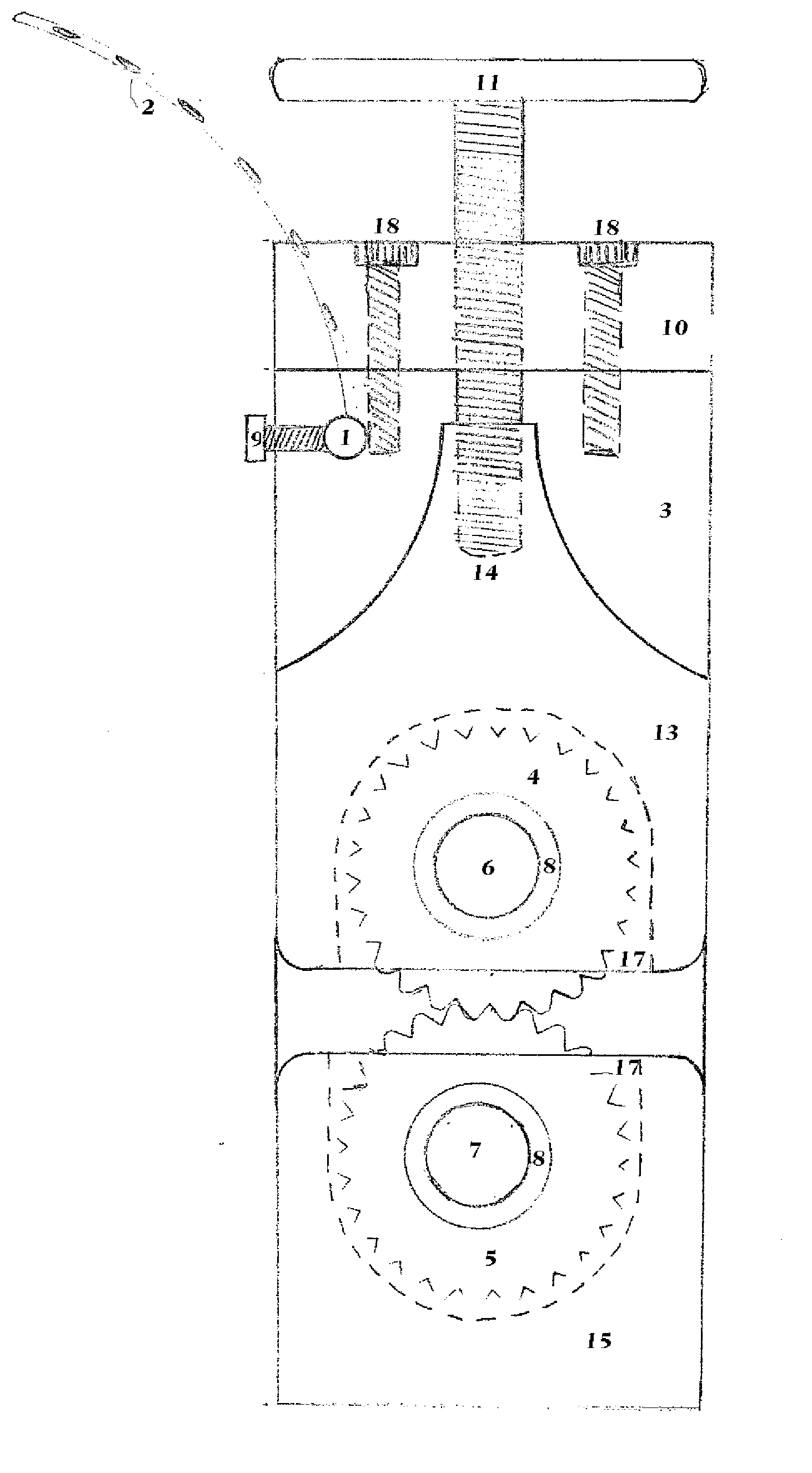
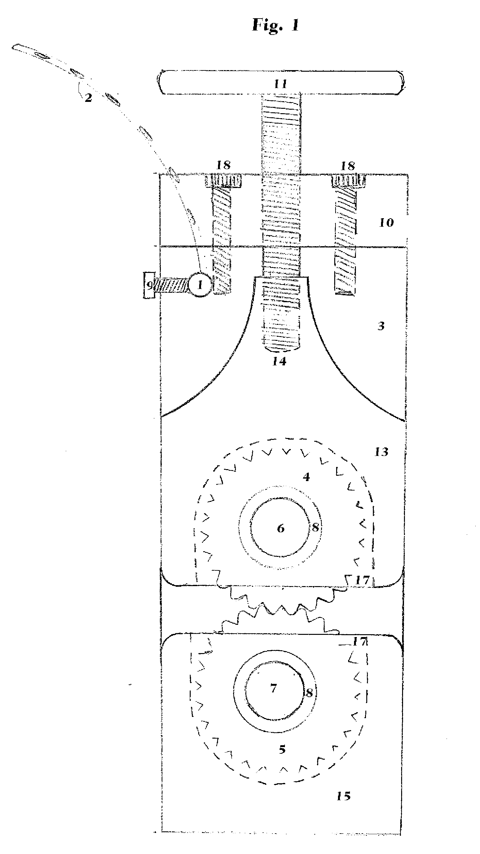
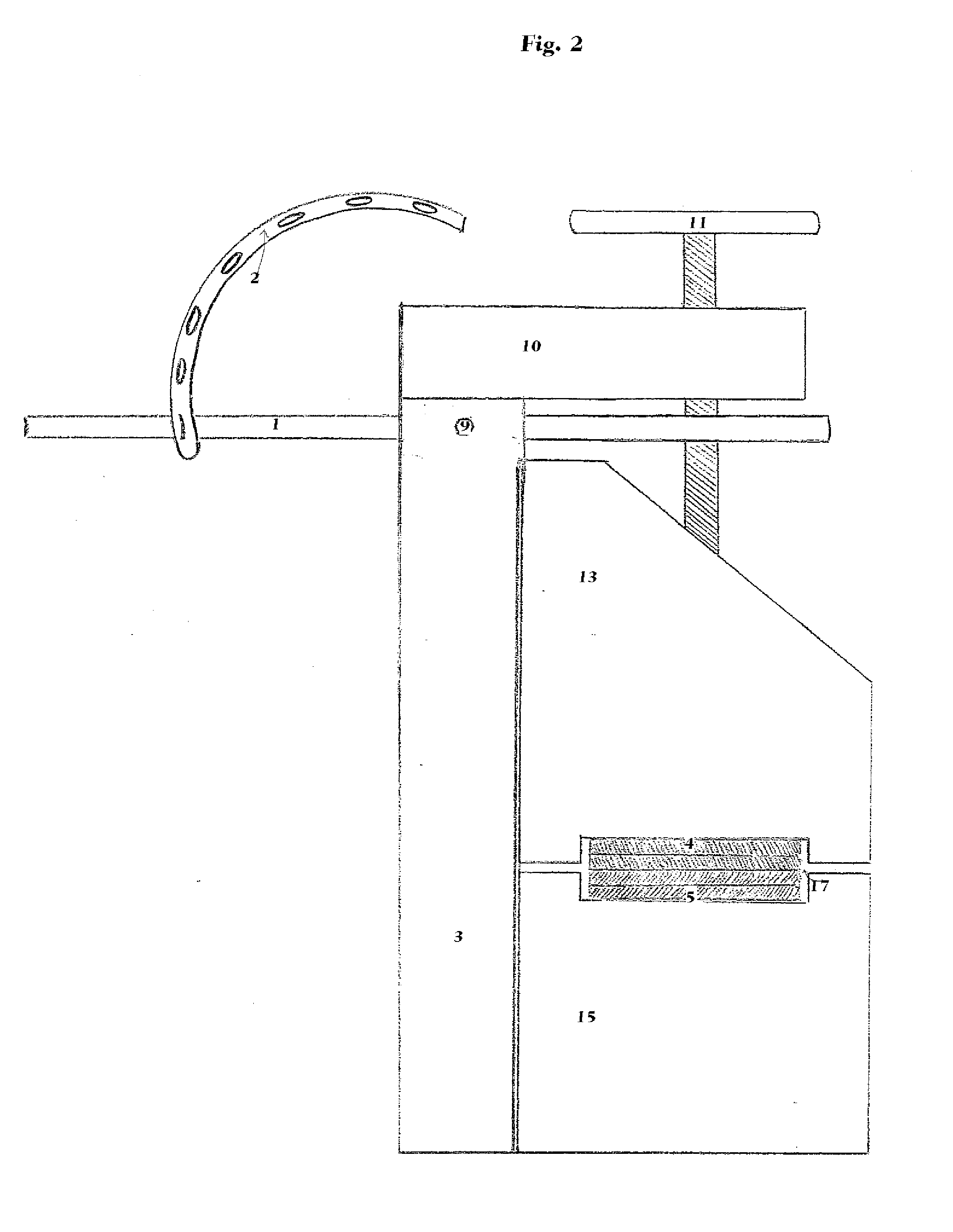
[0023]FIGS. 1 through 16 are perspective views of the crimping device constructed in accordance with the invention. An attached portion 1 is a steel rod used to brace the handle of a impact drill and secure the handle to the steel rod with a commercial grade rubber band with holes for adjustability like a belt and buckle. The steel rod 1 slides through a hole drilled into the track steel plate 3. The steel rod 1 is also adjustable in height due to different sized impact drills. The height can be adjusted by loosening the socket cap screw 9 and by either pulling or pushing the steel rod 1 until you've reached the desired height and re-tighten the socket cap screw 9. Back steel plate 10 is secured to the track steel plate 3 with two socket cap screws 9. The back steel plate 10 houses the threaded steel and T handle 11 used to separate and close the adjustable gear housing 13 to stationary gear housing 15 much like a table mounted vice clamp. The threaded steel portion of 11 leverages ...
PUM
| Property | Measurement | Unit |
|---|---|---|
| Diameter | aaaaa | aaaaa |
| Size | aaaaa | aaaaa |
Abstract
Description
Claims
Application Information
 - R&D
- Intellectual Property
- Life Sciences
- Materials
- Tech Scout
- Unparalleled Data Quality
- Higher Quality Content
- 60% Fewer Hallucinations
Browse by: Latest US Patents, China's latest patents, Technical Efficacy Thesaurus, Application Domain, Technology Topic, Popular Technical Reports.
© 2025 PatSnap. All rights reserved.Legal|Privacy policy|Modern Slavery Act Transparency Statement|Sitemap|About US| Contact US: help@patsnap.com


