Variable valve performance detection strategy for internal combustion engine

a technology of internal combustion engine and variable valve, which is applied in the direction of non-mechanical valves, electrical control, machines/engines, etc., can solve the problems of reducing the overall engine performance, affecting the performance of the engine, and affecting the operation efficiency of the engine,

Inactive Publication Date: 2008-04-24
CATERPILLAR INC
View PDF19 Cites 15 Cited by
  • Summary
  • Abstract
  • Description
  • Claims
  • Application Information

AI Technical Summary

Benefits of technology

[0009]In still another aspect, the present disclosure provides an internal combustion engine having at least two cylinders, intake valves in fluid communication with each of the at least two cylinders, and exhaust valves in fluid communication with each of the at least two cylinders. The engine further includes valve actuators configured to vary opening or closing timing of at least one of, the intake valves and the exhaust valves, and a computer configured to determine a performance status of at least one of, the intake valves and the exhaust valves, responsive to crankshaft acceleration of the engine.

Problems solved by technology

As is well known in the art, however, these systems do not always consistently perform precisely as desired, and the performance characteristics of variable valves can vary under certain conditions.
Variations in timing can degrade overall engine performance, and emissions quality, and can render certain operating schemes unachievable.
While such systems have performed relatively well over the years, they add expense and complexity to an engine system, and can suffer from reliability and warranty issues.

Method used


Image

  • Variable valve performance detection strategy for internal combustion engine
  • Variable valve performance detection strategy for internal combustion engine
  • Variable valve performance detection strategy for internal combustion engine

Examples


Embodiment Construction

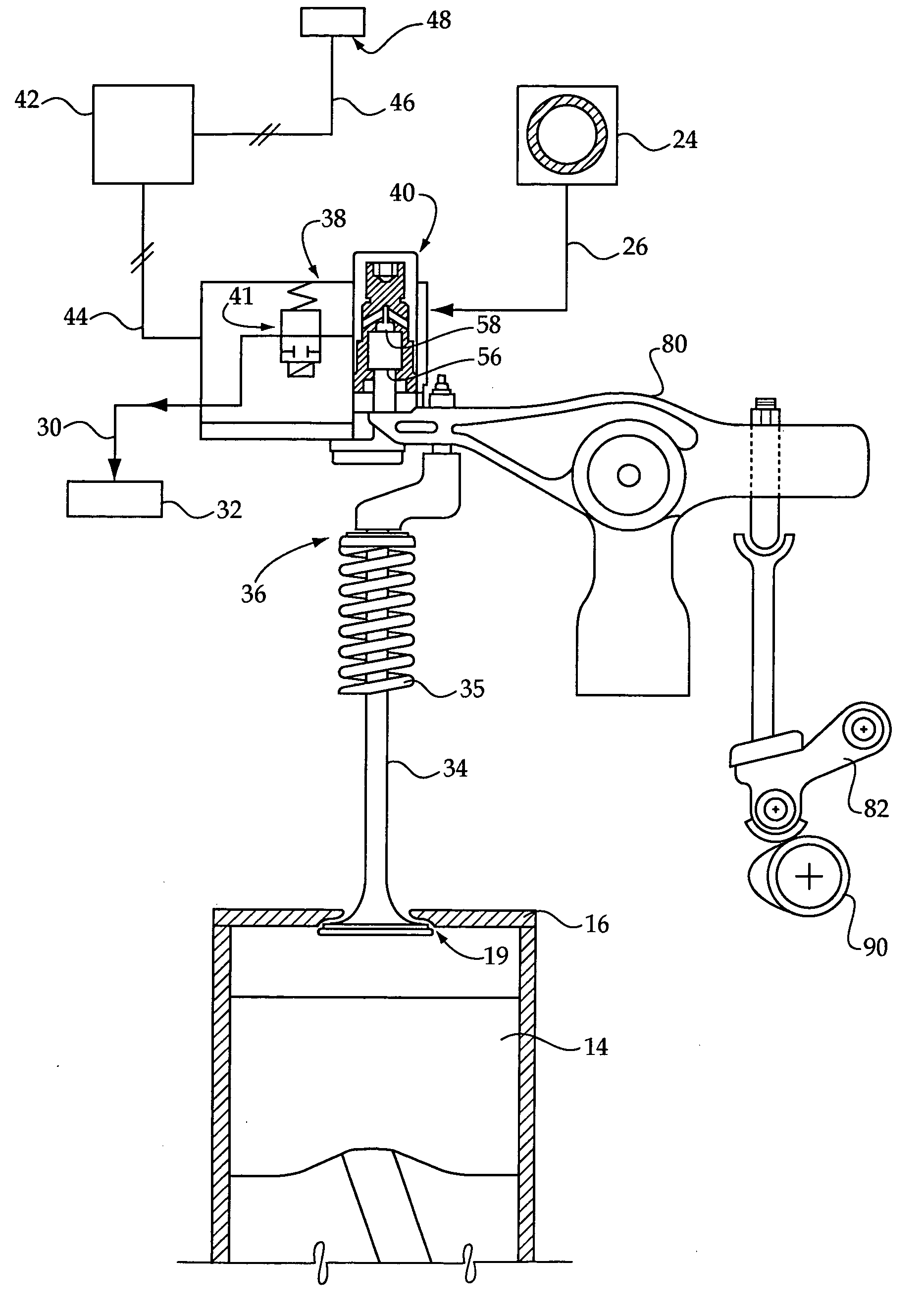
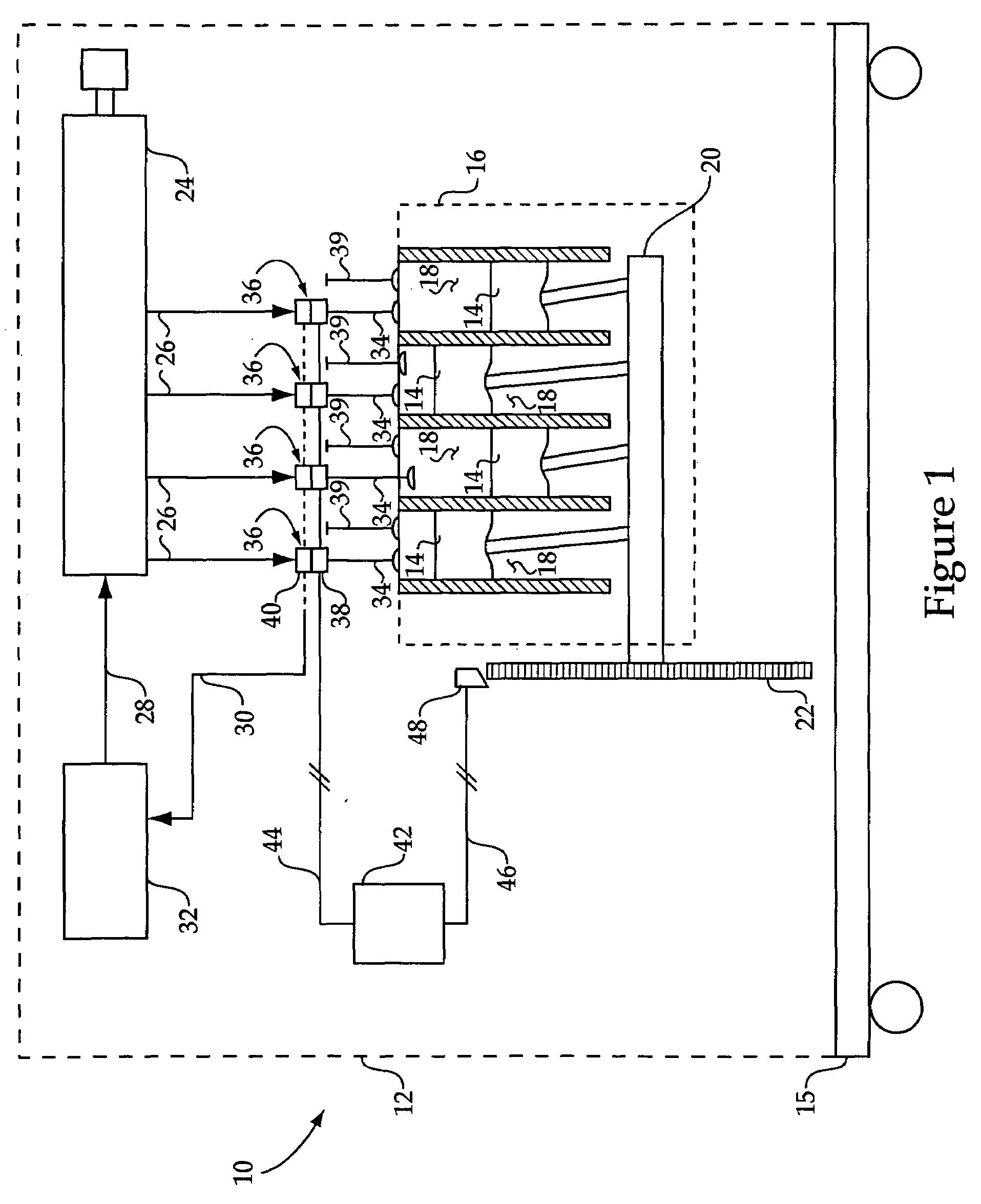
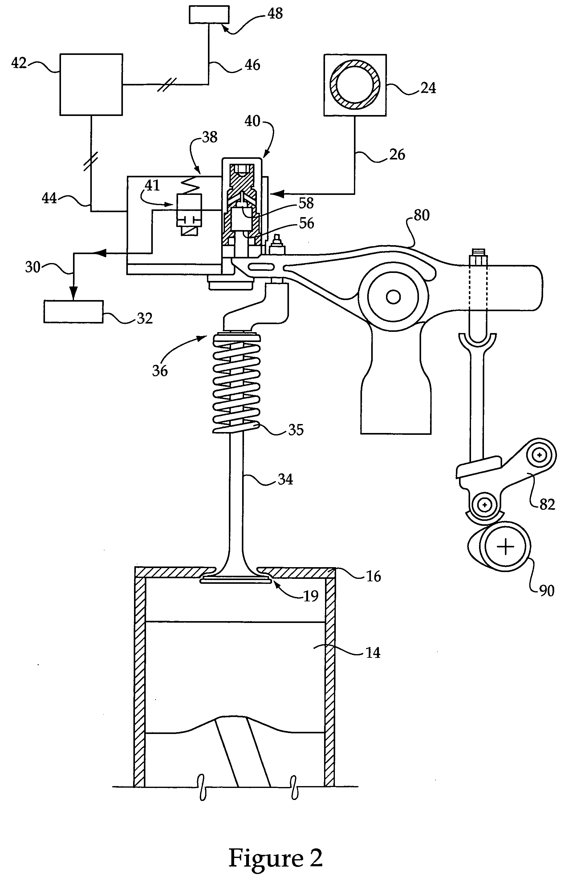
[0014]Referring to FIG. 1, there is shown a machine 10 having an engine system 12 according to the present disclosure. Engine system 12 may be mounted on a wheeled chassis 15, such as might be used in an on-highway truck or an off-road machine. It should be appreciated, however, that rather than a movable wheeled machine, machine 10 might be a stationary genset, pump, compressor or the like. Engine system 12 includes an engine housing 16 having a plurality of cylinders 18 therein, each including a movable piston 14 coupled with and configured to rotate a crankshaft 20. A plurality of engine valves 36 are positioned in fluid communication one with each of cylinders 18. Engine system 12 is shown in the context of a four cylinder in-line engine, however, a variety of other engine designs might be used without departing from the scope of the present disclosure. Engine system 12 is configured to determine a performance status of each of valves 36 and their associated cylinders 18, via mo...


PUM


Abstract

A method for operating a multi-cylinder internal combustion engine includes varying the opening or closing of engine valves including intake or exhaust valves, in fluid communication with each of the cylinders of the engine. The method further includes generating a signal indicative of engine valve status in response to monitoring an acceleration parameter of the engine. An engine includes a computer configured to determine a performance status of intake or exhaust valves of the engine responsive to monitoring an engine acceleration parameter such as crankshaft acceleration. The computer is configured via fault detection and cylinder trimming routines to adjust valve performance based on a nominal crankshaft acceleration for the engine.

Description

TECHNICAL FIELD[0001]The present disclosure relates generally to methods and systems for operating internal combustion engines having variable engine valves, and relates more particularly to a method of operating an intake or exhaust valve where its performance status is determined by monitoring engine crankshaft acceleration.BACKGROUND[0002]Variably timed intake and exhaust valves are used in a variety of engines, notably compression ignition internal combustion engines. Conventional engine systems utilize a rotating cam configured to control opening and / or closing of engine valves at desired times during an engine cycle. Variable valves provide some flexibility in opening or closing timing in such engine systems via actuators configured to control valve position separately from cam rotation. By varying the opening or closing timing of engine valves, operating strategies are enabled which can provide enhanced control over cylinder conditions during an engine cycle, enabling operati...

Claims


Application Information

Patent Timeline
Patent Type & Authority Applications(United States)
IPC IPC(8): F01L1/34
CPCF01L9/02F01L13/0015F01L2800/11F02D13/0207F02D41/0002F02D41/0085Y02T10/18F02D41/221F02D41/2464F02D2041/001F02D2200/1012Y02T10/42F02D41/1497F01L9/10Y02T10/12Y02T10/40
Inventor MUTTI, JAMES H.DEA, KEVIN L.GADBOIS, JOHN A.
Owner CATERPILLAR INC
Why Eureka
Try Eureka